
Programming instructions

Integration Technical Note 13
MITEL D/82 Station Set Emulation ©June 2003 Ericsson Enterprise AB
EN/LZT 108 6655 R1A
Installing the Dialogic D/82 Physical Interface
Installing the Dialogic D/82 Physical Interface Installing the Dialogic D/82 Physical Interface
Installing the Dialogic D/82 Physical Interface
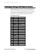
Each Dialogic D/82JCT-U card connects to the PBX with a Dialogic D/82-U
PBX interface cable assembly. One end of the cable is a 25-pair male RJ-21
connector; the other end is a Dialogic mini-D 36-pin connector that plugs into
the connector on the end plate of the Dialogic D/82 linecard. Table 3 shows the
wiring connections for the DNIC digital stations. The stations connect to the
even numbered pairs only. For additional information about installing the
linecard, refer to the spare parts document shipped with the linecard.
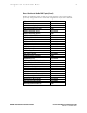
Table 3. Dialogic D/82 wire cut-down
Pair Color DNIC 430 stations
1 White/Blue
Blue/White
2 White/Oran
g
eT
(
Port 1
)
Oran
g
e/White R
(
Port 1
)
3 White/Green
Green/White
4 White/Brown T
(
Port 2
)
Brown/White R
(
Port 2
)
5 White/Slate
Slate/White
6 Red/Blue T
(
Port 3
)
Blue/Red R
(
Port 3
)
7 Red/Oran
g
e
Oran
g
e/Red
8 Red/Green T
(
Port 4
)
Green/Red R
(
Port 4
)
9 Red/Brown
Brown/Red
10 Red/Slate T
(
Port 5
)
Slate/Red R
(
Port 5
)
11 Black/Blue
Blue/Blac
k
12 Black/Oran
g
eT
(
Port 6
)
Oran
g
e/Blac
k
R
(
Port 6
)
13 Black/Green
Green/Blac
k
14 Black/Brown T
(
Port 7
)
Brown/Blac
k
R
(
Port 7
)
15 Black/Slate
Slate/Blac
k
16 Yellow/Blue T
(
Port 8
)
Blue/Yello
w
R
(
Port 8
)