Dialogic® 4000 Media Gateway Series Integration Note Mitel SX-2000 Lightware August 2008 64-0352-01 www.dialogic.
Copyright and Legal Notice Copyright © 2008 Dialogic Corporation. All Rights Reserved. You may not reproduce this document in whole or in part without permission in writing from Dialogic Corporation at the address provided below. All contents of this document are furnished for informational use only and are subject to change without notice and do not represent a commitment on the part of Dialogic Corporation or its subsidiaries (“Dialogic”).
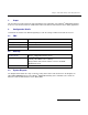
Dialogic® 4000 Media Gateway Series Integration Note 1. Scope ® This document is intended to detail a typical installation and configuration of the Dialogic 4000 Media Gateway ® Series if used to interface between a PBX and the Microsoft Office Communications Server (OCS) application. 2. Configuration Details Listed below are details of the PBX and gateways used in the testing on which this document is based. 2.1 PBX PBX Vendor Mitel Model(s) SX-2000 Lightware Software Version(s) Version 34.2.
Mitel SX-2000 Lightware OCS Clients 210 211 TDM Stations 350 351 IP LAN T1/E1 PBX 3. Prerequisites 3.1 PBX Prerequisites DMG4000 OCS Server The PBX must have all supplemental service packages installed for the Q.SIG protocol to operate properly and to provide all advanced supplemental services. 3.1.1 PBX Equipment Required To support the T1 Q.SIG configuration as documented you need a Mitel T1 line card. 3.1.2 PBX Cabling Requirements The cabling for Q.SIG connections must be CAT5e or better.
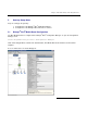
Dialogic® 4000 Media Gateway Series Integration Note 5. Gateway Setup Notes Steps for setting up the gateway: ® ® 1. Configuration of the Dialogic Diva Media Board drivers. ® ® ™ 2. Configuration of the Dialogic Diva SIPcontrol software. 5.1 Dialogic® Diva® Media Board Configuration ® ® The Diva Media Boards are configured in the Dialogic Diva Configuration Manager. To open the Configuration Manager, click: Start > Programs > Dialogic Diva > Configuration Manager.
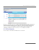
Mitel SX-2000 Lightware ® Note: The number of TDM circuits varies depending on the used Dialogic Media Gateway model. For this setup: • Set the property Switch Type to Q-SIG T1. • If your PBX does not provide ring tones to callers from TDM, set the property Generate Ring Tones to Yes. To activate the change, click File > Activate. ® Make these configuration changes for each TDM circuit you are going to use on the Dialogic Media Gateway. 5.
Dialogic® 4000 Media Gateway Series Integration Note The Network Interface Configuration will be used by the Diva SIPcontrol software for listening to the ® ® SIP traffic from Microsoft Mediation Server. Given that on these gateways the Microsoft Mediation Server component and the Diva SIPcontrol software are running in the same system, you will need to change SIP ® Listen port to 9803 or to an available un-used port.
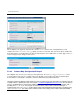
Mitel SX-2000 Lightware 5.2.3 Routing Configuration In the Routing Configuration section, you must create two routes, one for the inbound direction (TDM to IP) and one for the outbound direction (IP to TDM). Once you have created the routes, click the Save button for the changes to take effect. 5.2.4 Number Normalization The Dialplan Configuration and Address Map Configuration sections are used for manipulating dial numbers. For most PBX dialplans, an address map is required. See the following examples.
Dialogic® 4000 Media Gateway Series Integration Note 5.2.4.1 Dialplan Configuration Example To create a dialplan, click Add from the Dialplan Configuration. The following screens show how to set up ® a dialplan for a Microsoft Office Communications Server (OCS) 2007 application with the following dialplan from the PBX. (This may not match to the PBX programming in section 6 and the Setup in section 2.3).
Mitel SX-2000 Lightware For the dialplan to be applied to inbound calls, click the Details button of the configured SIP peer and configure the Address Normalization settings as in the screen below. This converts the phone number into ® the E.164 format as needed by Microsoft Office Communications Server 2007. Click OK on this page, and Save on the next page for the changes to take effect. 5.2.4.
Dialogic® 4000 Media Gateway Series Integration Note If the ISDN type of numbering flag is set to National, the prefix “N” will be used with the call number. If the type is Unknown, no prefix is used. Outbound call example using address maps: ® Microsoft Office Communications Server 2007 sends the E.164 dial number format to the SIP gateway. Both called and calling numbers need to be converted into a format that the PBX can accept.
Mitel SX-2000 Lightware The following screen shows the first sub rule that converts the E.164 calling number into a 10-digit national number: The following screen shows the second sub rule that converts E.
Dialogic® 4000 Media Gateway Series Integration Note The following sub rule converts the E.
Mitel SX-2000 Lightware Once an address map rule is created, it can be applied in three different places. To ease the configuration and troubleshooting processes, apply the rule on the outbound route as shown below: Inbound call example using address map: This example assumes that the PBX sends inbound calls using a 4-digit extension, with the ISDN type of number flag set to Subscriber for internal numbers, National for national calls, and International for international calls.
Dialogic® 4000 Media Gateway Series Integration Note Create an address map named Inbound and its four sub rules as shown below: 15
Mitel SX-2000 Lightware 16
Dialogic® 4000 Media Gateway Series Integration Note Apply the address map inbound rule on the inbound route as follows: 5.2.5 Restarting the Dialogic® Diva® SIPcontrol™ Software Note: A restart of the Diva SIPcontrol software service is needed only if the setting under Network Interface is changed. Save the configuration and restart the Diva SIPcontrol software service for the changes to take effect.
Mitel SX-2000 Lightware 6. PBX Setup Notes 6.1 Mitel SX-2000 Lightware ® This section provides information about the Dialogic 4000 Media Gateway Series PBX administration requirements for Mitel SX-2000 Light systems. This information includes: 1. 2. 3. 4. T1 Interface Administration Configure the Mitel SX-2000 Light for the T1 Q.
Dialogic® 4000 Media Gateway Series Integration Note 6.1.1 T1 Interface Administration There are three types of T1 interface administration required to properly program the Q.SIG integration on the ® Mitel SX-2000 Light system for the Dialogic 4000 Media Gateway Series: • • • SX-2000 Light Administration, Automatic Route Selection (ARS), and NSU Configurations / IMAT Programming. 6.1.1.1 SX-2000 Light Administration Step 1: Log into the Mitel SX-2000 Light system.
Mitel SX-2000 Lightware Select System Forms and press [ESC] then [1] to access the System Forms menu. Step 2: In the System Forms menu, select Dimension and Feature Select and press [ESC] then [2] to edit the Dimension and Feature Selection form.
Dialogic® 4000 Media Gateway Series Integration Note Configure the Dimension and Feature Selection as follows: Notes: • Parameters not listed below can be left at their default settings. • Q.SIG is a purchased option, so please verify that you have purchased Q.SIG before you continue. • • • Select Q-SIG, set it to Yes, and press [ENTER]. Press [ESC] then [4] to commit to changes and [ESC] then [1] to confirm the changes. Press [ESC] then [Q] to return to the System Forms menu.
Mitel SX-2000 Lightware Step 3: In the System Forms menu, select System Configuration and press [ESC] then [2] to edit the System Configuration form.
Dialogic® 4000 Media Gateway Series Integration Note • • • • Select the Cabinet number, the Shelf number, and the Slot number in which the T1 Q.SIG line is being installed. Set Programmed Card Type to Universal T1 and press [ENTER]. Press [ESC] then [4] to commit to changes and [ESC] then [1] to confirm the changes. Press [ESC] then [Q] to return to the System Forms menu.
Mitel SX-2000 Lightware • • • • • • • 24 Set Class of service number: to an unused class of service number. Press [ESC] then [1] to create the new class of service.
Dialogic® 4000 Media Gateway Series Integration Note Step 5: In the Customer Data Entry menu, select Digital Link Forms and press [ESC] then [1] to access the Digital Link Form menu. In the Digital Link Forms menu, select Link Descriptor Assignment and press [ESC] then [1] to edit the Link Descriptor Assignment form.
Mitel SX-2000 Lightware Configure the form as follows: Note: Parameters not listed below can be left at their default settings. • • 26 Set Digital Link Descriptor Number to an unused digital link descriptor number. Set Address for Message Control to A.
Dialogic® 4000 Media Gateway Series Integration Note • • • • • • • • • • Set Integrated Digital Access to ISDN Node. Set QSIG Private Network Access to Yes. Set Termination Mode to NT. Set Operation Mode to CSU. Set CSU Tx Line Build-Out (dB.) to 0. Set Extended Super Frame to Yes. Set Inverted D Channel to No. Set Voice Conversion to Invert. Press [ESC] then [4] to commit to changes and [ESC] then [1] to confirm the changes. Press [ESC] then [Q] to return to the Digital Link Forms menu.
Mitel SX-2000 Lightware • • • • • • 28 As Link number select 1, and as Cabinet number, Shlf number, and Slot number select the numbers in which the T1 Q.SIG line is being installed. Set Digital Link Descriptor Number to the link descriptor assignment number defined in Step 5 of the SX-2000 Light Administration and press [ENTER]. The Text field can be left blank or a description of the link can be entered. Press [ESC] then [4] to commit to changes and [ESC] then [1] to confirm the changes.
Dialogic® 4000 Media Gateway Series Integration Note Step 7: In the Customer Data Entry menu, select System Forms and press [ESC] then [2] to access the System Forms menu. In the System Forms menu, select System Options Assignment and press [ESC] then [2] to edit the System Options Assignment form.
Mitel SX-2000 Lightware Configure the form as follows: Note: Parameters not listed below can be left at their default settings. • • • • 30 Set Route Optimization Network Id to a string of digits that needs to have the same length as the phone extension, and press [ENTER]. Press [ESC] then [4] to commit to changes and [ESC] then [1] to confirm the changes. Press [ESC] then [Q] to return to the System Forms menu.
Dialogic® 4000 Media Gateway Series Integration Note Step 8: In the Customer Data Entry menu, select Trunk Forms and press [ESC] then [1] to access the Trunk Forms menu. In the Trunk Forms menu, select MSDN-DPNSS-DASSII Trunk Circuit Descriptor Assignment and press [ESC] then [2] to edit the MSDN-DPNSS-DASSII Trunk Circuit Descriptor Assignment form.
Mitel SX-2000 Lightware Note: Parameters not listed below can be left at their default settings. • • • • • • • 32 Set Trunk Circuit Descriptor Number to an unused trunk circuit descriptor number. Set Signaling Protocol to MSDN-DPNSS. Set Dual Seizure Priority to Incoming. Set Far End Connection to Local Office. Set Card Type to Universal T1. Press [ESC] then [4] to commit to changes and [ESC] then [1] to confirm the changes. Press [ESC] then [Q] to return to the Trunk Forms menu.
Dialogic® 4000 Media Gateway Series Integration Note Step 9: In the Trunk Forms menu, select Trunk Service Assignment and press [ESC] then [2] to edit the Trunk Service Assignment form.
Mitel SX-2000 Lightware Note: Parameters not listed below can be left at their default settings. • • • • • • Select an unused Trunk Service No. Set COS (Class of Service) to the class of service number defined in Step 4 of the SX-2000 Light Administration. Set COR (Class of Restriction) to a valid class of restriction number. Set Absorb to 0. Press [ESC] then [4] to commit to changes and [ESC] then [1] to confirm the changes. Press [ESC] then [Q] to return to the Trunk Forms menu.
Dialogic® 4000 Media Gateway Series Integration Note Configure the form as follows: Note: Parameters not listed below can be left at their default settings. • • • • • • • • • • • • • • • Select as Circuit number 1, and as Cabinet number, Shelf number, and Slot number the number in which the T1 QSIG line is being installed. Set Trunk Num to an unused trunk number that has at least 22 unused trunk numbers available after it (e.g., if you select 100, 101-122 must also be available).
Mitel SX-2000 Lightware • • Press [ESC] then [4] to commit to changes and [ESC] then [1] to confirm the changes. Press [ESC] then [Q] to return to the Trunk Forms menu. Step 11: In the Trunk Forms menu, select Trunk Group Assignment and press [ESC] then [2] to edit the Trunk Group Assignment form.
Dialogic® 4000 Media Gateway Series Integration Note Note: Parameters not listed below can be left at their default settings. • • • • • • • • • • • Set Trunk Group Number to an unused trunk group number. Set Hunt Mode to Terminal. Press [ESC] then [1] to recall a list of members. Set Member # 1 to the first trunk number defined in Step 10 of the SX-2000 Light Administration. Press [ESC] then [2] to define the range programming, RANGE PROGRAMMING Parameters data entry field will appear in the main screen.
Mitel SX-2000 Lightware 6.1.1.2 Automatic Route Selection (ARS) Step 1: Log into the Mitel SX-2000 Light system. Press [ESC] then [7] to access the Customer Data Entry menu.
Dialogic® 4000 Media Gateway Series Integration Note Select Automatic Route Selection Forms and press [ESC] then [1] to access the ARS Forms menu.
Mitel SX-2000 Lightware Step 2: In the ARS menu, select Digital Modification Assignment and press [ESC] then [2] to edit the Digital Modification Assignment form.
Dialogic® 4000 Media Gateway Series Integration Note Note: Parameters not listed below can be left at their default settings. • • • • Select an unused digital modification number. Set the Number of Digits to Absorb to 0. Press [ESC] then [4] to commit to changes and [ESC] then [1] to confirm the changes. Press [ESC] then [Q] to return to the ARS Forms menu. Step 3: In the ARS menu, select Route Assignment and press [ESC] then [2] to edit the Route Assignment form.
Mitel SX-2000 Lightware Note: Parameters not listed below can be left at their default settings. • • • • • • • 42 Select an unused Route Number. Set Trunk Group Number to the trunk group number defined in Step 11 of the SX-2000 Light Administration. Set COR Group Number to 1. Set Digit Modification Number to the digital modification number defined in Step 2 of the Automatic Route Selection. Set Digits Before Outpulsing to 5.
Dialogic® 4000 Media Gateway Series Integration Note Step 4: In the ARS menu, select Automatic Route Selection Assignment and press [ESC] then [2] to edit the Automatic Route Selection Assignment form.
Mitel SX-2000 Lightware Note: Parameters not listed below can be left at their default settings. • • • • • • • • Set Leading Digits to a currently unassigned ARS number. Set Digits Dialed to an unused 2-digit string. Set Number of Digits to Follow to 2. Set Termination Type to Route. Set Termination Number to 2. Press [ESC] then [4] to commit to changes and [ESC] then [1] to confirm the changes. Press [ESC] then [Q] to return to the ARS Forms menu.
Dialogic® 4000 Media Gateway Series Integration Note • • Select the appropriate version of the database based on the version of Mitel SX-2000 Light Software being used. If you use the SX-2000 Light software version 34.2.0.20, select from the dropdown menu under ISDN/PRI System the Universal NSU Release 1.5. Click OK to create the new database. Step 2: Configure the Site Options as follows: Select Config > System Configuration > Site Options. • • Under System Type, select Universal NSU.
Mitel SX-2000 Lightware • • Under Options, select Network-side Interface and Qsig. Click Update and then Close. Step 3: Configure the PRI Link Characteristics as follows: Select Config > System Configuration > PRI Link Characteristics. Note: Parameters not listed below can be left at their default settings. • • • • • • • 46 Set PRI link number* to the link number in which the T1 Q.SIG is installed. Set Protocol Type to QSIG. Set Protocol Variant to ISO. Set Physical Type to T1/CSU.
Dialogic® 4000 Media Gateway Series Integration Note • • • • • Under Line Coding, select B8ZS. Under Framing, select ESF. Under Line Build Out, select 0 dB. Under Invert Data, select Disable. Click Update and Close. Step 4: Configure the Incoming Call Characteristics as follows: Select Config > Incoming Call Characteristics. • • • • • Set PRI link number* to the link number that the T1 QSIG is installed. Set Trunks* to 1-23. Set DDI Delivery to Yes. Set CPN Delivery to Yes. Click Update and Close.
Mitel SX-2000 Lightware Step 5: Configure the Outgoing Call Characteristics as follows: Select Config > Outgoing Call Characteristics. Note: Parameters not listed below can be left at their default settings. • • • 48 Set PRI link number* to the link number on which the T1 Q.SIG is installed. Under Fixed Bearer Capability, set the parameter Voice to Speech. Click Update and Close.
Dialogic® 4000 Media Gateway Series Integration Note Step 6: Configure the Connection to Remote Sites as follows: Select File > Connect to Remote Site. Note: Parameters not listed below can be left at their default settings. • • • • • Set Connection Medium to Ethernet Network Card. Under Network Settings, enter the IP address of the 3300 Universal NSU (The default value is 192.168.1.1.). Set Ethernet Remote System to PRI Card / Universal NSU. Click Connect.
Mitel SX-2000 Lightware Step 7: Save the database as follows: Click File > Save > Database. • • Set Destinations to PRI Card / Universal NSU. Click Save. Note: If a dialog box appears stating “Are you sure you want to save this OLDER version of IMAT Database? select DO NOT UPGRADE to the latest database Version and Save and click OK. Click OK at the Information dialog box stating that the database has been sent.
Dialogic® 4000 Media Gateway Series Integration Note Click Maintenance > Remote Site Reset. Click the Reset button. Click OK in the Information dialog box stating that IMAT is “Disconnected from remote site.” Click OK in the dialog box stating that the remote site is resetting.
Mitel SX-2000 Lightware 7. Microsoft® Office Communications Server 2007 (OCS) Setup 7.1 Steps for configuring Microsoft® OCS ® Normalization rules are used to convert dial numbers into full E.164 formatted numbers. Microsoft OCS uses the standard E.164 format to search for users listed in the Active Directory (AD). ® If a Microsoft OCS user dials an internal extension number (normally 3-5 digits), the normalization rules convert it into full E.164 format.
Dialogic® 4000 Media Gateway Series Integration Note Click Add or Edit to create or change a particular rule.
Mitel SX-2000 Lightware In this example, when a user dials any 4-digit number, it will be converted to its E.164 equivalent of +1716639xxxx and then that number will be searched for in AD.
Dialogic® 4000 Media Gateway Series Integration Note More examples are shown in the following table: Name Phone Pattern Translation Pattern Comments Extensions ^(\d{4})$ +1716639$1 Internal extensions Local ^(\d{7})$ +1716$1 Local number National ^1(\d*)$ +1$1 Long distance number International ^011(\d*) +$1 International number ® A default route is used to route all calls to Microsoft Mediation Server.
Mitel SX-2000 Lightware ® This entry routes numbers with or without “+” prefix followed by any digits to Microsoft Mediation Server dmg4000.bufocs.local. Restart the Front End Services for the above changes to take effect, including all normalization rules. This can be done from the window Services. ® ® Note: Unless the dialed number from Microsoft OCS client (such as Microsoft Office Communicator) is in E.164 ® format, Microsoft OCS must find a normalization rule to convert the dialed number to E.164.
Dialogic® 4000 Media Gateway Series Integration Note ® ® or matched, outbound calls will fail. In this case, Dialogic Diva Diagnostics trace will not receive an outbound SIP message, since the call will not yet have reached the SIP gateway. 7.2 Steps for configuring Microsoft® Office Communications Server 2007 (OCS) clients ® The domain users need to be enabled for making calls through Microsoft OCS.
Mitel SX-2000 Lightware Under the Communications tab, check the Enable user for Office Communications Server option and then click the Configure button.
Dialogic® 4000 Media Gateway Series Integration Note 8. Microsoft® Mediation Server Installation and Configuration 8.1 Installation ® The gateways of the Dialogic 4000 Media Gateway Series (DMG4000 Gateways) are shipped with pre-installed ® ® Microsoft Mediation Server software. You can complete the Microsoft Mediation Server configuration by ® running Microsoft Office Communications Server 2007 (OCS) “Setup.exe” in the DMG4000 Gateways.
Mitel SX-2000 Lightware ® 4. Create the certificate request for the Microsoft Mediation Server: • Run Deployment Wizard, click step 4. • Select the option Create a new certificate. • Select the option Send the request immediately to an online CA. • Complete the settings in the blank. • Click Assign to complete the task.
Dialogic® 4000 Media Gateway Series Integration Note 8.2 Configuration ® From the MMC snap-in, right-click the detected Microsoft Mediation Server and select Properties.
Mitel SX-2000 Lightware Configure the following settings on the General tab: 62
Dialogic® 4000 Media Gateway Series Integration Note Click the Next Hop Connections tab and configure the following: ® The Port entry under PSTN Gateway Next hop has to match the configuration in the Dialogic Diva SIPcontrol™ Software under Network Interface Configuration > SIP Listen Port.
Mitel SX-2000 Lightware Click the Certificate tab. ® ® Select the certificate that will be used to communicate with Microsoft OCS. Microsoft Mediation Server will need to restart for these changes to properly take effect. 9. Testing the Validation Matrix ® The table below shows various test scenarios that are run as typical validation scenarios if the Dialogic Media Gateway is used in a voice messaging situation. The notes column specifies any notable parts of the test.
Dialogic® 4000 Media Gateway Series Integration Note Test Number Call Scenario Description Notes Inbound call scenarios 1 Direct call from TDM station set to ® Microsoft OCS client. 2 Direct call from Microsoft OCS client to TDM station set. ® 10. Troubleshooting 10.1 Important Debugging Tools • • • 10.2 Ethereal/Wireshark: Can be used to view and analyze the network captures provided by the Dialogic gateway diagnostic firmware.
Mitel SX-2000 Lightware ® ® 1. Click one line of your Dialogic Diva Media Board in the left pane and click the Basic tracing level. This level captures Q.931 ISDN messages. on the toolbar to activate 2. Click CAPI driver in the left pane and activate the Basic tracing level as explained in step 1. 3. Start tracing. To do so, click the start icon menu. or select the Start Tracing option form the Tracing 4. Reproduce the issue. 5. To stop tracing, click the stop icon Tracing menu.
Dialogic® 4000 Media Gateway Series Integration Note ® ® ® Examples of Dialogic Diva Diagnostics traces for an inbound (TDM to IP) call to Microsoft Office Communications Server 2007 (OCS) Basic notations for reading the trace: • • • • SIG-R: RX Q.931 ISDN message SIG-X: TX Q.931 ISDN message SIPR: RX SIP message SIPX: TX SIP message < Below is a RX Q.931 ISDN message for an inbound call > … 9:16:28.
Mitel SX-2000 Lightware 9:16:28.431 1 L 12 00010000-SIPR begin (331 byte) from IP:192.168.0.106 PORT:5060 on socket 3 port 5060 TCP 9:16:28.431 1 L 12 00010000>SIP/2.0 100 Trying 9:16:28.431 1 L 12 00010000>FROM: "Dialogic Diva SIPcontrol";tag=sipcontrol_2617534104-7668808 9:16:28.431 1 L 12 00010000>TO: "Default" 9:16:28.431 1 L 12 00010000>CSEQ: 1 INVITE 9:16:28.
Dialogic® 4000 Media Gateway Series Integration Note 9:16:30.197 9:16:30.197 9:16:30.197 9:16:30.197 9:16:30.197 9:16:30.197 9:16:30.197 9:16:30.197 9:16:30.197 9:16:30.197 9:16:30.197 9:16:30.197 9:16:30.197 9:16:30.197 9:16:30.197 9:16:30.197 9:16:30.197 9:16:30.197 9:16:30.197 … 1 1 1 1 1 1 1 1 1 1 1 1 1 1 1 1 1 1 1 L L L L L L L L L L L L L L L L L L L 12 12 12 12 12 12 12 12 12 12 12 12 12 12 12 12 12 12 12 00010000>ALLOW: UPDATE 00010000>SERVER: RTCC/3.0.0.
Mitel SX-2000 Lightware 70