
User`s guide


22 Dialogic
®
1000 and 2000 Media Gateway Series Getting Started Guide
Dialogic Corporation
Controls, Indicators, and Connectors
1.4.4 COM 1 and COM 2 Connectors
COM 1 and COM 2 are DB9 serial port connectors. The COM 1 port is used for interfacing to PBX
Serial Integration Protocols. The COM 2 port is used for interfacing to a diagnostics/administration
terminal. Refer to the User’s Guide for configuration information. See Table 4 for the connector
pin designations.
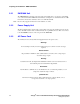
1.4.5 LAN1 and LAN2 (Ethernet) Port
The LAN1 connector is a shielded 8-pin modular phone jack that allows you to connect to a 10/100
BaseT Ethernet. This interface can be used to connect to the unit to VoIP endpoints and to connect
users to the units maintenance interface. The LAN2 connector is a shielded 8-pin modular phone
jack that allows you to connect to a 10/100 BaseT Ethernet. This interface can be used to connect
users to the units maintenance interface.
Note: Currently, the LAN2 connector is only supported in Version 5.1 SU1 Software or later.
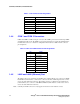
Table 3. T1/E1 Connector Pin Designations
Pin Description
1 RCV_RING
2 RCV_TIP
3 No connection
4XMIT_RING
5 XMIT_TIP
6 No connection
7 No connection
8 No connection
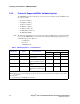
Table 4. COM 1 and COM 2 Connector Pin Designations
Pin Signal
1 Data Carrier Detect
2 Transmit Data
3 Receive Data
4 Data Terminal Ready
5 Signal Ground
6 Data Set Ready
7 Clear to Send
8 Request to Send
9 Ring Indicator