
User`s guide


Dialogic
®
1000 and 2000 Media Gateway Series Getting Started Guide 21
Dialogic Corporation
Controls, Indicators, and Connectors
• Fast Flashing Green - indicates that there is activity on the port.
• Steady Orange - indicates that frame is in sync.
• Medium Flashing Between Green and Orange - indicates that frame is in sync and waiting
for ISDN D-channel to come up.
• Steady Green - indicates that operational layer is in sync.
• Steady Red - indicates that no carrier is present.
1.4 Rear Panel Controls, Indicators, and Connectors for
DMG2000 Models
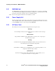
The rear panel controls, indicators, and connectors, Figure 4, include:
• AC Power Connector
• AC Power Switch
• T1/E1 Connectors
• COM 1 and COM 2 Connectors
• LAN1 and LAN2 (Ethernet) Port
Figure 4. Rear Panel - DMG2000 Models
1.4.1 AC Power Connector
The AC Power Connector supports either the 115 VAC commonly used in NA or the 220 VAC
commonly used in EU. See Section 3.2.2, “AC Power Cord”, on page 28 for details regarding the
power cord shipped with the unit
1.4.2 AC Power Switch
The AC power switch is a two position rocker switch that, when in the on (I) position, applies
power to the unit.
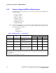
1.4.3 T1/E1 Connectors
The T1/E1 connectors are RJ-45 connectors that provide connections to T1 or E1 trunks. See
Table 3 for the connector pin designations.
LAN
1
2
COM 1
COM 2
T1/E1
2143