
User`s guide


Dialogic
®
1000 and 2000 Media Gateway Series Getting Started Guide 15
Dialogic Corporation
1
Controls, Indicators, and
Connectors
This chapter provides information about the controls, indicators, and connectors for both the
Dialogic
®
1000 Media Gateway (DMG1000) and Dialogic
®
2000 Media Gateway (DMG2000)
models in the following sections:
• Front Panel Indicators for DMG1000 Models. . . . . . . . . . . . . . . . . . . . . . . . . . . . . . . . 15
• Rear Panel Controls, Indicators, and Connectors for DMG1000 Models . . . . . . . . . . . 17
• Front Panel Indicators for DMG2000 Models. . . . . . . . . . . . . . . . . . . . . . . . . . . . . . . . 19
• Rear Panel Controls, Indicators, and Connectors for DMG2000 Models . . . . . . . . . . . 21
1.1 Front Panel Indicators for DMG1000 Models
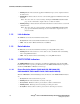
The front panel LED indicators, Figure 1, include:
1. Ready Indicator
2. Link Indicator
3. Data Indicator
4. PORT STATUS Indicators
Figure 1. Front Panel - DMG1000 Models
1.1.1 Ready Indicator
The Ready indicator is a multicolored LED that shows the unit’s system status, where:
• Unlit - indicates that the unit is not powered on.
• Steady Red - indicates that the unit is in the power-on initialization stage.
• Steady Green - indicates that power-on initialization is complete and the unit is awaiting
application load.
1
23
45 6
78
PORT STATUS
Ready
Link
Data