
Network Card User Manual
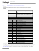
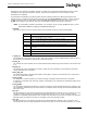
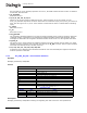
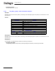

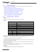
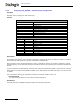
Table Of Contents
- Dialogic® DSI SS7MD Network Interface Board Programmer's Manual
- Contents
- Chapter 1: Introduction
- Chapter 2: Specification
- Chapter 3: Installation
- Chapter 4: Dialogic® DSI SS7MD Board Configuration and Operation
- 4.1 Regulatory and Geographic Considerations
- 4.2 System Structure
- 4.3 Running Host Binaries With Dialogic® DSI SS7MD Board
- 4.4 System Configuration
- 4.5 Protocol Configuration
- 4.6 Monitoring
- 4.7 ATM Monitoring
- 4.8 Switching Timeslots between LIUs
- 4.9 Received Message Timestamping
- 4.10 High Speed Link Operation
- 4.11 Operation of the Thermal Sensor
- Chapter 5: Program Execution
- Chapter 6: Message Reference
- Chapter 7: Configuration Command Reference
- 7.1 Physical Interface Configuration Commands
- 7.2 Monitor Configuration Commands
- 7.3 MTP Configuration Commands
- 7.4 ATM Configuration Commands
- 7.5 ISUP Configuration Commands
- 7.6 TUP Configuration Commands
- 7.7 SCCP Configuration Commands
- 7.8 DTC Configuration Commands
- 7.9 TCAP Configuration Commands
- 7.10 MAP Configuration Commands
- 7.11 INAP Configuration Commands
- 7.12 IS41 Configuration Commands
- Chapter 8: Host Utilities
- Appendix A: Protocol Configuration Using Discrete Messages
- Appendix B: Thermal guidelines for selecting suitable servers for use with a Dialogic® DSI SS7MDL4 Network Interface Board
- Glossary
- Index
74
6 Message Reference
the loop delay in ms for 56 kbits/s operation. If set to 0, the MTP2 module assumes a value of 12800 for
an HSL link, 400 otherwise.
• rtv_attempts
Reserved. Set to 0.
• t1, t2, t3, t4n, t4e, t5, t6, t7
Values for the protocol timers as defined in Q.703. These should be set to the number of (tick *
timer_res) intervals required for the timer. The timers are checked for expiry every timer_res number of
ticks. The value given for t1, t2 etc. is the number of times that the timer is checked before indicating
expiry.
• t_suerm
Reserved. Set to 0.
• t_rtv
Reserved. Set to 0.
• cong_discard
The congestion discard threshold for use with the single message priority mode of operation. When the
combined number of messages in the transmit and retransmit buffers reaches this threshold, further
messages are discarded. The congestion discard threshold cannot be set to a value greater than 4160.
• l3_link_id
The value to use in the ID field of all indications issued to the upper module (that is, MTP3). For single
signaling processor systems, this is typically the same as the l2_llid. However, when a system contains
more than one MTP2 processor, this may not be so.
• co1, co2, co3, ca1, ca2, ca3, cd1, cd2, cd3
Congestion onset, abatement and discard thresholds for use when the Multiple Congestion Thresholds
mode of operation is selected.
6.4.2 API_MSG_RX_IND – Received Data Indication
Synopsis
Message generated by MTP2/ATM.
Format
Description
Message generated by MTP2/ATM containing the Signaling Unit data received on the specified link.
MESSAGE HEADER
FIELD NAME MEANING
type API_MSG_RX_IND (0x8f01)
id l3_link_id/upper_id
src MTP2 module ID/ATM module ID
dst Links upper module ID/user module ID
rsp_req 0
hclass 0
status 0
err_info 0
next 0
len
Number of octets in the Signaling Unit. For AAL5 Monitoring equals
number of octets in the Signaling Unit + 2.
PARAMETER AREA
OFFSET SIZE NAME
0 len- /len - 2 Signaling Unit (SU) data in binary format.
/len - 2 0/1 UUI - User to User Indication - AAL5 Monitoring parameter only
/len - 1 0/1 CPI - Common Part Indicator - AAL5 Monitoring parameter only