
Network Card User Manual
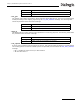

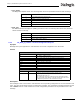
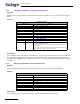
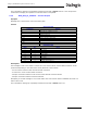
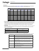
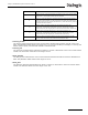
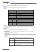
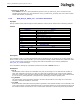
Table Of Contents
- Dialogic® DSI SS7MD Network Interface Board Programmer's Manual
- Contents
- Chapter 1: Introduction
- Chapter 2: Specification
- Chapter 3: Installation
- Chapter 4: Dialogic® DSI SS7MD Board Configuration and Operation
- 4.1 Regulatory and Geographic Considerations
- 4.2 System Structure
- 4.3 Running Host Binaries With Dialogic® DSI SS7MD Board
- 4.4 System Configuration
- 4.5 Protocol Configuration
- 4.6 Monitoring
- 4.7 ATM Monitoring
- 4.8 Switching Timeslots between LIUs
- 4.9 Received Message Timestamping
- 4.10 High Speed Link Operation
- 4.11 Operation of the Thermal Sensor
- Chapter 5: Program Execution
- Chapter 6: Message Reference
- Chapter 7: Configuration Command Reference
- 7.1 Physical Interface Configuration Commands
- 7.2 Monitor Configuration Commands
- 7.3 MTP Configuration Commands
- 7.4 ATM Configuration Commands
- 7.5 ISUP Configuration Commands
- 7.6 TUP Configuration Commands
- 7.7 SCCP Configuration Commands
- 7.8 DTC Configuration Commands
- 7.9 TCAP Configuration Commands
- 7.10 MAP Configuration Commands
- 7.11 INAP Configuration Commands
- 7.12 IS41 Configuration Commands
- Chapter 8: Host Utilities
- Appendix A: Protocol Configuration Using Discrete Messages
- Appendix B: Thermal guidelines for selecting suitable servers for use with a Dialogic® DSI SS7MDL4 Network Interface Board
- Glossary
- Index
70
6 Message Reference
• mode
The mode of operation that controls how the switch channels are allocated. Typically, when mode is set
to 1, the first timeslot connected to the switch is connected to the timeslot indicated by sc_channel
and each subsequent timeslot that is connected will be connected to the next switch channel. This
allows maximum utilization of channels on the switch.
An alternative, with mode set to 2, which should only be used if there is a specific requirement for it,
associates (but does not necessarily connect) timeslot 0 on the LIU with the switch timeslot specified by
sc_channel and subsequent timeslots on the LIU with subsequent switch channels. Connections are
only made when the corresponding bit in the timeslot mask is set to 1. This mode of operation preserves
the spacing between timeslots that was originally found on the T1/E1/J1 interface, but does result in a
number of switch channels not being used.
6.3.9 MVD_MSG_SC_LISTEN – Cross Connect Switch Listen Request
Synopsis
Establish a connection from an cross connect switch channel to an outgoing timeslot on an T1/E1/J1 Line
Interface Unit (LIU).
Format
Description
This message is sent to the board to establish a connection between a switch channel to an outgoing timeslot
on the T1/E1/J1 Line Interface Unit (LIU).
Parameters
• liu_id
The identifier of the T1/E1/J1 Line Interface Unit (LIU) in the range of 0 to one less than the number of
LIUs.
• timeslot
The timeslot number of the T1/E1/J1 Line Interface Unit (LIU) on which the data from the switch channel
will be transmitted. Valid ranges are:
— For a T1 Interface: 1 to 24
— For a E1 Interface: 1 to 31
— For a J1 Interface: 1 to 24
• sc_channel
The channel number on the switch to which the LIU will listen. This should be in the range of 0 to one
less than the total number of channels provided by the cross connect switch.
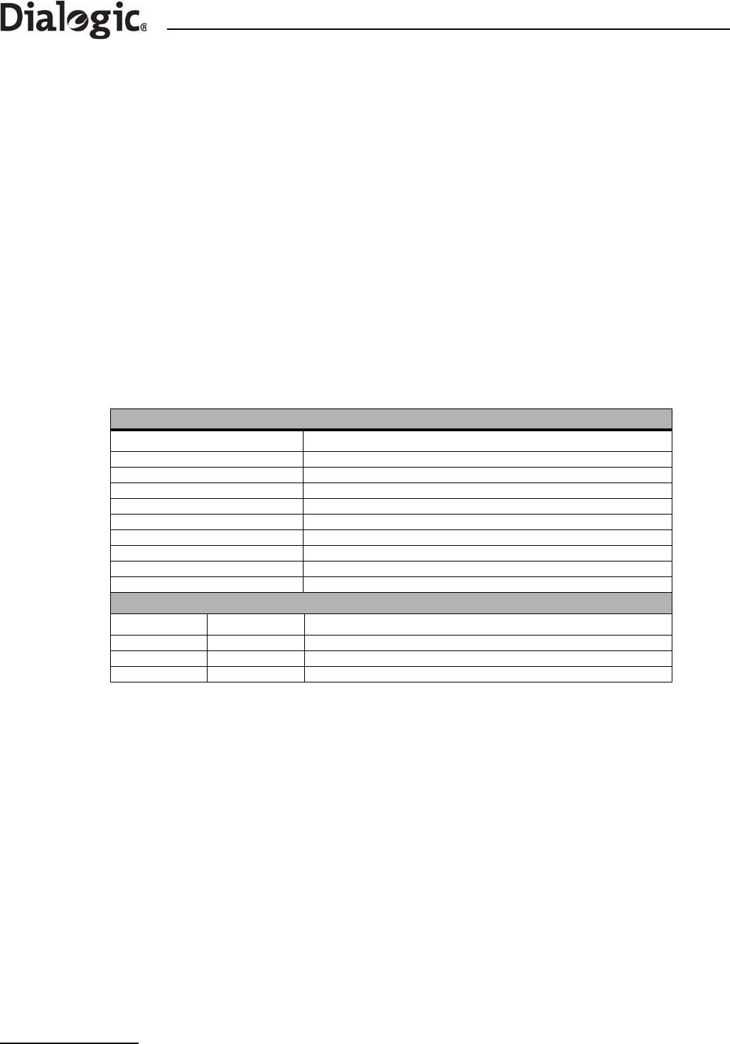
MESSAGE HEADER
Field Name Meaning
Type MVD_MSG_SC_LISTEN (0x7e17)
Id 0
Src Sending module's Id
Dst MVD_TASK_ID
Rsp_req Used to request a confirmation
Hclass 0
Status 0
Err_info 0
Len 6
PARAMETER AREA
Offset Size Name
0 2 liu_id
2 2 timeslot
4 4 sc_channel