
Network Card User Manual

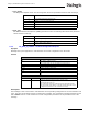
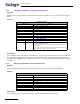
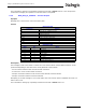
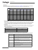
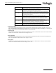
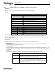
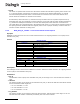
Table Of Contents
- Dialogic® DSI SS7MD Network Interface Board Programmer's Manual
- Contents
- Chapter 1: Introduction
- Chapter 2: Specification
- Chapter 3: Installation
- Chapter 4: Dialogic® DSI SS7MD Board Configuration and Operation
- 4.1 Regulatory and Geographic Considerations
- 4.2 System Structure
- 4.3 Running Host Binaries With Dialogic® DSI SS7MD Board
- 4.4 System Configuration
- 4.5 Protocol Configuration
- 4.6 Monitoring
- 4.7 ATM Monitoring
- 4.8 Switching Timeslots between LIUs
- 4.9 Received Message Timestamping
- 4.10 High Speed Link Operation
- 4.11 Operation of the Thermal Sensor
- Chapter 5: Program Execution
- Chapter 6: Message Reference
- Chapter 7: Configuration Command Reference
- 7.1 Physical Interface Configuration Commands
- 7.2 Monitor Configuration Commands
- 7.3 MTP Configuration Commands
- 7.4 ATM Configuration Commands
- 7.5 ISUP Configuration Commands
- 7.6 TUP Configuration Commands
- 7.7 SCCP Configuration Commands
- 7.8 DTC Configuration Commands
- 7.9 TCAP Configuration Commands
- 7.10 MAP Configuration Commands
- 7.11 INAP Configuration Commands
- 7.12 IS41 Configuration Commands
- Chapter 8: Host Utilities
- Appendix A: Protocol Configuration Using Discrete Messages
- Appendix B: Thermal guidelines for selecting suitable servers for use with a Dialogic® DSI SS7MDL4 Network Interface Board
- Glossary
- Index

68
6 Message Reference
6.3.7 MVD_MSG_SC_MULTI_CONNECT – Multiple Connect Request
Synopsis
Message sent to the board to control the switch to connect multiple paths.
Format
Description
This message is sent to the board in order to control the configuration of the cross connect switch for more
complex configurations.
Parameters
The MVD_MSG_SC_MULTI_CONNECT message includes the following parameters:
• local_stream
The logical reference of the local stream that the message relates to, that is, 0 to one less than the
number LIUs corresponding to the liu_id.
• timeslot_mask
A 32-bit mask representing up to 32 timeslots on the local stream. Bit 0 corresponds to timeslot 0. A 1 in
the mask indicates that the pattern should be output on this timeslot, a 0 indicates that it should be left
unchanged.
• mode
The mode of operation. The following table shows the permitted values and their meaning.
MESSAGE HEADER
Field Name Meaning
type MVD_MSG_SC_MULTI_CONNECT (0x7e19)
id 0
src Sending module ID
dst MVD_module_ID
rsp_req May be used to request a confirmation.
hclass 0
status 0
err_info 0
len 18
PARAMETER AREA
Offset Size Name
0 2 local_stream
2 4 timeslot_mask
62mode
82source_st
10 2 source_ts
12 6 Reserved. Must be set to 0.
Value Description
1
Make a simplex connection between an cross connect switch timeslot and a local
LIU stream. Use the local_stream and timeslot_mask to specify the target
destination on the CPU local bus. The source_st and source_ts.
11
Make a simplex connection between two CPU local bus stream timeslots. The
source_st and source_ts parameters specify the source of the signal in terms of
liu_id or CPU local bus stream reference and timeslots, respectively. The
local_stream relates to the outgoing liu_id stream and cannot reference a CPU local
bus stream. The timeslot_mask parameters specify the outgoing timeslots to which
the source will be connected.