
Network Card User Manual
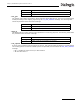

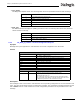
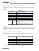
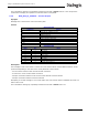
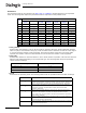
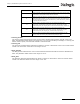
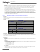
Table Of Contents
- Dialogic® DSI SS7MD Network Interface Board Programmer's Manual
- Contents
- Chapter 1: Introduction
- Chapter 2: Specification
- Chapter 3: Installation
- Chapter 4: Dialogic® DSI SS7MD Board Configuration and Operation
- 4.1 Regulatory and Geographic Considerations
- 4.2 System Structure
- 4.3 Running Host Binaries With Dialogic® DSI SS7MD Board
- 4.4 System Configuration
- 4.5 Protocol Configuration
- 4.6 Monitoring
- 4.7 ATM Monitoring
- 4.8 Switching Timeslots between LIUs
- 4.9 Received Message Timestamping
- 4.10 High Speed Link Operation
- 4.11 Operation of the Thermal Sensor
- Chapter 5: Program Execution
- Chapter 6: Message Reference
- Chapter 7: Configuration Command Reference
- 7.1 Physical Interface Configuration Commands
- 7.2 Monitor Configuration Commands
- 7.3 MTP Configuration Commands
- 7.4 ATM Configuration Commands
- 7.5 ISUP Configuration Commands
- 7.6 TUP Configuration Commands
- 7.7 SCCP Configuration Commands
- 7.8 DTC Configuration Commands
- 7.9 TCAP Configuration Commands
- 7.10 MAP Configuration Commands
- 7.11 INAP Configuration Commands
- 7.12 IS41 Configuration Commands
- Chapter 8: Host Utilities
- Appendix A: Protocol Configuration Using Discrete Messages
- Appendix B: Thermal guidelines for selecting suitable servers for use with a Dialogic® DSI SS7MDL4 Network Interface Board
- Glossary
- Index
67
Dialogic
®
DSI SS7MD Programmer’s Manual Issue 3
• source_stream
The source_stream references the cross connect switch streams that should be used as a source for
data. The parameter takes values in the range of 0 to 31. For some modes (for example, 11 and 12), this
field is used to specify a local stream instead of a switch stream.
• source_slot
The source slot references the timeslot from which to connect or disconnect to the cross connect switch
stream. The source slot values are in the range 0 to 127.
• dest_stream
The dest_stream references the cross connect switch streams that should be used as a destination for
data. The parameter takes values in the range of 0 to 31.
• dest_slot
The dest slot references the timeslot from which to connect or disconnect to the cross connect switch
stream. The dest slot values are in the range of 0 to 127.
6
Remove a duplex connection between two timeslots on the cross connect switch
and one timeslot on the CPU local bus. Use the local_stream and local_slot
parameters to specify both timeslots for disconnection.
8
Remove a connection between a switch timeslot and a CPU local bus timeslot.
Then create a simplex connection between the same CPU local bus timeslot
back to the switch timeslot. Use the local_stream and local_slot parameters to
specify the CPU local bus timeslot, and the source_stream and source_timeslot
to specify the switch timeslot.
11
Make a simplex connection between two CPU local bus timeslots. The
source_stream and source_slot parameters specify the source of the signal in
terms of liu_id and timeslot, respectively. The local_stream and local_slot
parameters specify the outgoing lLIU or CPU stream and timeslot, respectively.
12
Make a duplex connection between two CPU local bus timeslots. The
source_stream and source_slot parameters specify the source of the signal in
terms of liu_id and timeslot, respectively. The local_stream and local_slot
parameters specify the outgoing liu_id and timeslot, respectively
13
Remove a duplex connection between two CPU local bus timeslots. Use the
local_stream and local_slot parameters to specify one timeslot and the
source_stream and source_slot parameters to specify the other.
Value Meaning