
Network Card User Manual
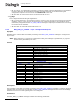
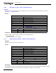
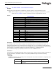
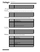
Table Of Contents
- Dialogic® DSI SS7MD Network Interface Board Programmer's Manual
- Contents
- Chapter 1: Introduction
- Chapter 2: Specification
- Chapter 3: Installation
- Chapter 4: Dialogic® DSI SS7MD Board Configuration and Operation
- 4.1 Regulatory and Geographic Considerations
- 4.2 System Structure
- 4.3 Running Host Binaries With Dialogic® DSI SS7MD Board
- 4.4 System Configuration
- 4.5 Protocol Configuration
- 4.6 Monitoring
- 4.7 ATM Monitoring
- 4.8 Switching Timeslots between LIUs
- 4.9 Received Message Timestamping
- 4.10 High Speed Link Operation
- 4.11 Operation of the Thermal Sensor
- Chapter 5: Program Execution
- Chapter 6: Message Reference
- Chapter 7: Configuration Command Reference
- 7.1 Physical Interface Configuration Commands
- 7.2 Monitor Configuration Commands
- 7.3 MTP Configuration Commands
- 7.4 ATM Configuration Commands
- 7.5 ISUP Configuration Commands
- 7.6 TUP Configuration Commands
- 7.7 SCCP Configuration Commands
- 7.8 DTC Configuration Commands
- 7.9 TCAP Configuration Commands
- 7.10 MAP Configuration Commands
- 7.11 INAP Configuration Commands
- 7.12 IS41 Configuration Commands
- Chapter 8: Host Utilities
- Appendix A: Protocol Configuration Using Discrete Messages
- Appendix B: Thermal guidelines for selecting suitable servers for use with a Dialogic® DSI SS7MDL4 Network Interface Board
- Glossary
- Index
55
Dialogic
®
DSI SS7MD Programmer’s Manual Issue 3
Configure the LSL timeslot rate:
• l1_resource_id
Layer 1 (logical) resource identifier.
• data_rate
Used for setting the link operation. The following table shows the permitted values and their meaning.
• link_source
Configure the signaling source.
Set to 0 for DSI SS7MD Board.
• link_stream
Signaling stream. This parameter is the physical identity of the T1/E1/J1 line interface containing the
signaling link. The value range is 0 to one less than the number of LIUs.
• link_timeslot
Signaling timeslot. This field is used to configure conventional SS7 links. The value ranges for
link_timeslot are:
— For a T1 interface: 1 to 24.
— For an E1 interface: 1 to 31.
— For a J1 interface: 1 to 24.
• options
A 32-bit value containing run-time options as follows:
— Bit 0 - Set to 1 to disable automatic FISU generation. This is normally required for Japanese MTP
operation only.
— Bit 1 - Set to 1 to enable onboard time stamping on monitored links. Setting this bit changes the
MSG type of the monitor message from API_MSG_RX_IND to API_MSG_RX_INDT.
— Bit 4 - HSL operation. Set to 0 for 7-bit sequence numbers. Set to 1 for 12-bit sequence numbers.
— Bit 6 - HSL operation. Set to 0 for LSL SS7. Set to 1 for HSL SS7.
— All Other Bits - Must be set to 0.
• timeslot_mask
Signaling timeslot mask. This field is used to configure HSL links. Bits 0 to 31 of the mask correspond to
timeslots 0 to 31 of the signaling stream identified by the link_stream parameter. The recommended
bits masks values are:
Value Data Rate
0 64 kbits/s
1 56 kbits/s
2 48 kbits/s
Value Description
0xfffffffe structured E1 HSL, 31 slots (1 to 31)
0x01fffffe structured T1 HSL, 24 slots (1 to 24)
0xfffefffe structured E1 HSL, 30 slots (1 to 15,17 to 31)