
Network Card User Manual
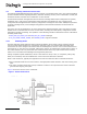
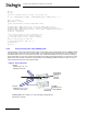
Table Of Contents
- Dialogic® DSI SS7MD Network Interface Board Programmer's Manual
- Contents
- Chapter 1: Introduction
- Chapter 2: Specification
- Chapter 3: Installation
- Chapter 4: Dialogic® DSI SS7MD Board Configuration and Operation
- 4.1 Regulatory and Geographic Considerations
- 4.2 System Structure
- 4.3 Running Host Binaries With Dialogic® DSI SS7MD Board
- 4.4 System Configuration
- 4.5 Protocol Configuration
- 4.6 Monitoring
- 4.7 ATM Monitoring
- 4.8 Switching Timeslots between LIUs
- 4.9 Received Message Timestamping
- 4.10 High Speed Link Operation
- 4.11 Operation of the Thermal Sensor
- Chapter 5: Program Execution
- Chapter 6: Message Reference
- Chapter 7: Configuration Command Reference
- 7.1 Physical Interface Configuration Commands
- 7.2 Monitor Configuration Commands
- 7.3 MTP Configuration Commands
- 7.4 ATM Configuration Commands
- 7.5 ISUP Configuration Commands
- 7.6 TUP Configuration Commands
- 7.7 SCCP Configuration Commands
- 7.8 DTC Configuration Commands
- 7.9 TCAP Configuration Commands
- 7.10 MAP Configuration Commands
- 7.11 INAP Configuration Commands
- 7.12 IS41 Configuration Commands
- Chapter 8: Host Utilities
- Appendix A: Protocol Configuration Using Discrete Messages
- Appendix B: Thermal guidelines for selecting suitable servers for use with a Dialogic® DSI SS7MDL4 Network Interface Board
- Glossary
- Index

35
Dialogic
®
DSI SS7MD Programmer’s Manual Issue 3
4.7 ATM Monitoring
The system can also be used to monitor AAL5 traffic that is running over ATM links.
The following is an example config.txt configuration file to support AAL5 Monitoring:
********************************************************************************
* Example Protocol Configuration File (config.txt) for use with
* Dialogic(R) DSI SS7MD Network Interface Boards.
********************************************************************************
*
* SS7_BOARD <board_id> <board_type> <flags> <code_file> <run_mode>
SS7_BOARD 0 SS7MD 0x0001 ss7.dc6 ATM
*
* LIU_CONFIG <board_id> <liu_id> <liu_type> <line_code> <frame_format> <crc_mode> [<build_out>]
LIU_CONFIG 0 0 6 1 1 1 0
*
* ATM_CONFIG <options> <num_streams>
ATM_CONFIG 0x0000 4
*
*
* ATM_STREAM <id> <board_id> <cellstream_id> <liu_id> <options> <ima_frame_len> <max_frame_len>
* <def_vpi> <def_vci> <timeslot>
ATM_STREAM 3 0 1 0 0x00 0 280 12 10 0xfffefffe
*
* MONITOR_LINK <link_id> <board_id> <blink> <atm_stream> <VPI-VCI> <user_module> <filter>
* <flags> <phys_mask> ATM
MONITOR_LINK 0 0 0 9 9-128 0x0d 0 0x0000 0x00 ATM
*
********************************************************************************
The underlying ATM system is configured using the ATM_CONFIG command. The links to be used are then
specified using the ATM_STREAM command and monitoring is established for these links using the
MONITOR_LINK command.
4.7.1 IMA Monitoring
When configuring IMA Monitoring, the maximum limit is 31 monitoring links per IMA bundle.