
Network Card User Manual
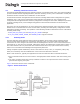
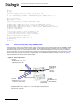
Table Of Contents
- Dialogic® DSI SS7MD Network Interface Board Programmer's Manual
- Contents
- Chapter 1: Introduction
- Chapter 2: Specification
- Chapter 3: Installation
- Chapter 4: Dialogic® DSI SS7MD Board Configuration and Operation
- 4.1 Regulatory and Geographic Considerations
- 4.2 System Structure
- 4.3 Running Host Binaries With Dialogic® DSI SS7MD Board
- 4.4 System Configuration
- 4.5 Protocol Configuration
- 4.6 Monitoring
- 4.7 ATM Monitoring
- 4.8 Switching Timeslots between LIUs
- 4.9 Received Message Timestamping
- 4.10 High Speed Link Operation
- 4.11 Operation of the Thermal Sensor
- Chapter 5: Program Execution
- Chapter 6: Message Reference
- Chapter 7: Configuration Command Reference
- 7.1 Physical Interface Configuration Commands
- 7.2 Monitor Configuration Commands
- 7.3 MTP Configuration Commands
- 7.4 ATM Configuration Commands
- 7.5 ISUP Configuration Commands
- 7.6 TUP Configuration Commands
- 7.7 SCCP Configuration Commands
- 7.8 DTC Configuration Commands
- 7.9 TCAP Configuration Commands
- 7.10 MAP Configuration Commands
- 7.11 INAP Configuration Commands
- 7.12 IS41 Configuration Commands
- Chapter 8: Host Utilities
- Appendix A: Protocol Configuration Using Discrete Messages
- Appendix B: Thermal guidelines for selecting suitable servers for use with a Dialogic® DSI SS7MDL4 Network Interface Board
- Glossary
- Index

34
4 Dialogic® DSI SS7MD Board Configuration and Operation
4.6 Monitoring
The monitoring option can be used in conjunction with the SS7 Development Package for the appropriate
operating system (Linux or Solaris) to realize a high-performance protocol monitor with up to 4 boards, each
monitoring a certain number of links (see the table in Section 2.3.1, “Run Modes” on page 15 for details).
When used in a passive monitoring mode, the DSI SS7MD Boards treat the signaling timeslot as an HDLC
channel so, in addition to SS7, other flag-idle HDLC-based protocols may be monitored, for example LAPB,
Q.931 (ISDN PRI) and DPNSS. The protocol to be monitored must have a minimum frame length (excluding
flags) of 5 octets, a maximum of 278 octets, and use the CRC polynomial (x
16
+ x
12
+ x
5
+ 1). When
operating in monitoring mode, the 3rd and successive identical frames may be filtered.
It is possible to configure monitoring and terminated SS7 links on the same signaling card.
4.6.1 Configuration
The user needs to set up the configuration for the T1/E1/J1 interface and the operating parameters for each
link to be monitored. This can be achieved using the config.txt file in conjunction with the s7_mgt configuration
utility. Users wishing to use discrete message-based configuration should refer to Section A.2, “Monitoring
Configuration Using Individual Messages” on page 180 of this manual.
4.6.2 Runtime Operations
Once configured, whenever a frame is received, it is reported to the user’s application as an
API_MSG_RX_IND or API_MSG_RX_INDT (timestamped) message.
During operation, the user may also read (and optionally reset) various statistics on a per-link basis by
sending a Link Statistics Request (DVR_MSG_R_L1_STATS) message.