
Network Card User Manual
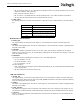

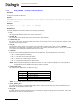
Table Of Contents
- Dialogic® DSI SS7MD Network Interface Board Programmer's Manual
- Contents
- Chapter 1: Introduction
- Chapter 2: Specification
- Chapter 3: Installation
- Chapter 4: Dialogic® DSI SS7MD Board Configuration and Operation
- 4.1 Regulatory and Geographic Considerations
- 4.2 System Structure
- 4.3 Running Host Binaries With Dialogic® DSI SS7MD Board
- 4.4 System Configuration
- 4.5 Protocol Configuration
- 4.6 Monitoring
- 4.7 ATM Monitoring
- 4.8 Switching Timeslots between LIUs
- 4.9 Received Message Timestamping
- 4.10 High Speed Link Operation
- 4.11 Operation of the Thermal Sensor
- Chapter 5: Program Execution
- Chapter 6: Message Reference
- Chapter 7: Configuration Command Reference
- 7.1 Physical Interface Configuration Commands
- 7.2 Monitor Configuration Commands
- 7.3 MTP Configuration Commands
- 7.4 ATM Configuration Commands
- 7.5 ISUP Configuration Commands
- 7.6 TUP Configuration Commands
- 7.7 SCCP Configuration Commands
- 7.8 DTC Configuration Commands
- 7.9 TCAP Configuration Commands
- 7.10 MAP Configuration Commands
- 7.11 INAP Configuration Commands
- 7.12 IS41 Configuration Commands
- Chapter 8: Host Utilities
- Appendix A: Protocol Configuration Using Discrete Messages
- Appendix B: Thermal guidelines for selecting suitable servers for use with a Dialogic® DSI SS7MDL4 Network Interface Board
- Glossary
- Index
133
Dialogic
®
DSI SS7MD Programmer’s Manual Issue 3
— Bit 12 is used to select 12- or 7-bit sequence numbers for HSL only. This bit should be set for 12-bit
sequence numbers, clear otherwise.
— Bits 13 and 14 reserved. Set to 0.
— Bit 15 is set to 1 to disable the link. This bit should be set to 0 to enable normal link operation.
— All other bits are reserved for future use and should be set to 0.
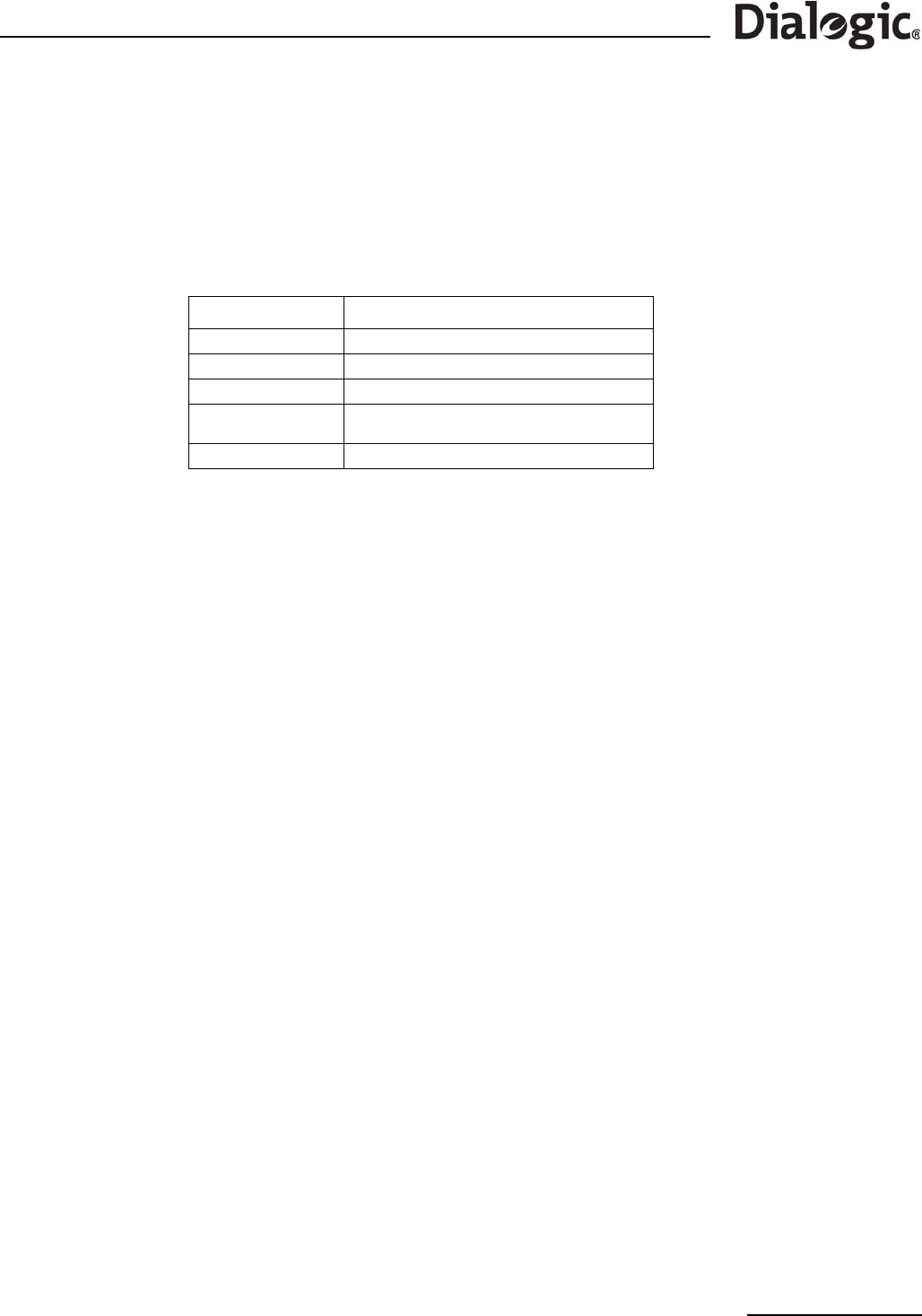
• <data_rate>
An optional parameter to specify link parameters, required for HSL or ATM operation. The valid values
are:
MTP HSL/LSL Link Parameters
• <board_id>
The logical identity of the board in the range 0 to one less than the number of boards supported.
• <blink>
The index of the signaling link. It must be in the range 0 to one less than the number of signaling links
licensed on the board.
• <stream>
When the <timeslot> parameter is set to a non-zero value, the <stream> parameter is the logical
identity of the T1/E1/J1 LIU (liu_id) containing the signaling link. It should be in the range 0 to one less
than the number of LIUs.
• <timeslot>
The timeslot used for signaling in the range 0 to 31. The valid ranges are:
— For a T1 interface: 1 to 24.
— For an E1 interface: 1 to 31.
— For a J1 interface: 1 to 24.
For HSL operation:
— 0xff - Data rate is set using the optional data rate parameter, if not present data rate defaults based
on LIU type (T1/E1).
— All other values are reserved for future use.
ATM Link Parameters
• <board_id>
The logical identity of the board in the range from 0 to one less than the number of boards supported.
This should be the same value as used in the ATM_STREAM command. If the value selected is different,
then the configuration will be rejected.
• <blink>
The index of the signaling link. It must be in the range 0 to one less than the number of signaling links
licensed on the board.
• <atm_stream>
This defines the logical id of the cell stream over which the link runs. It must be in the range 0 to one
less than the combined number of ATM Cell Streams supported by all the SS7MD boards in the system.
• <vpi-vci >
This is a compound parameter that identifies the VPI and VCI of the ATM link. It is represented in the
form vpi-vci where:
Value Description
TDM single timeslot SS7 LSL (default)
E1_FRAMED HSL structured 31 slot E1 operation
T1_FRAMED HSL structured 24 slot T1/J1 operation
E1_PCM
HSL structured 30 slot E1 operation (where
timeslots 0 and 16 are not used for signaling)
ATM The command follows the syntax for ATM links