
Network Card User Manual

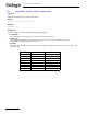
Table Of Contents
- Dialogic® DSI SS7MD Network Interface Board Programmer's Manual
- Contents
- Chapter 1: Introduction
- Chapter 2: Specification
- Chapter 3: Installation
- Chapter 4: Dialogic® DSI SS7MD Board Configuration and Operation
- 4.1 Regulatory and Geographic Considerations
- 4.2 System Structure
- 4.3 Running Host Binaries With Dialogic® DSI SS7MD Board
- 4.4 System Configuration
- 4.5 Protocol Configuration
- 4.6 Monitoring
- 4.7 ATM Monitoring
- 4.8 Switching Timeslots between LIUs
- 4.9 Received Message Timestamping
- 4.10 High Speed Link Operation
- 4.11 Operation of the Thermal Sensor
- Chapter 5: Program Execution
- Chapter 6: Message Reference
- Chapter 7: Configuration Command Reference
- 7.1 Physical Interface Configuration Commands
- 7.2 Monitor Configuration Commands
- 7.3 MTP Configuration Commands
- 7.4 ATM Configuration Commands
- 7.5 ISUP Configuration Commands
- 7.6 TUP Configuration Commands
- 7.7 SCCP Configuration Commands
- 7.8 DTC Configuration Commands
- 7.9 TCAP Configuration Commands
- 7.10 MAP Configuration Commands
- 7.11 INAP Configuration Commands
- 7.12 IS41 Configuration Commands
- Chapter 8: Host Utilities
- Appendix A: Protocol Configuration Using Discrete Messages
- Appendix B: Thermal guidelines for selecting suitable servers for use with a Dialogic® DSI SS7MDL4 Network Interface Board
- Glossary
- Index

132
7 Configuration Command Reference
Syntax
MTP HSL/LSL Links
MTP_LINK <link_id> <linkset_id> <link_ref> <slc> <board_id> <blink> <stream> <timeslot> <flags>
[<data_rate>]
Example
MTP_LINK 0 0 0 0 0 0 0 16 0x0006 TDM
ATM Links
MTP_LINK <link_id> <linkset_id> <link_ref> <slc> <board_id> <blink> <atm_stream> <vpi-vci> <flags> ATM
Example
MTP_LINK 0 0 0 0 3 0 0 8-100 0x0006 ATM
Common Parameters
The MTP_LINK command includes the following parameters:
• <link_id>
The unique logical identity of the link. It must be in the range 0 to one less than the total number of
signaling links supported.
• <linkset_id>
The logical identity of the linkset to which the link belongs. The linkset must already have been
configured using the MTP_LINKSET command.
• <link_ref>
The logical identity within the linkset of the signaling link. It should be in the range 0 to one less than the
number of links in the linkset.
• <slc>
The signaling link code for the signaling link. This must be unique within the linkset and is typically the
same as <link_ref>. The valid range is 0 to 15.
• <flags>
A 32-bit value containing additional run-time options. The bit significance is as follows:
Note: If the <data_rate> is set to "ATM", only bits 0 to 2 are significant.
— Bit 0 is set to 1 to force the use of the emergency proving period during link alignment or 0 to use
the appropriate proving period according to the MTP3 recommendations.
— Bit 1 is set to 1 to cause a signaling link test (in accordance with ITU-T Q.707 / ANSI T1.111.7) to be
carried out before a link is put into service, or 0 if a test is not required.
— Bit 2 is set to 1 to cause a signaling link test (in accordance with ITU-T Q.707 / ANSI T1.111.7) to be
carried out every 30 seconds. This bit is ignored unless bit 1 is set to 1.
— Bit 8 is used to select the MTP2 error correction mode. It is set to 1 to select PCR (Preventive Cyclic
Retransmission) operation or 0 for the Basic Method of Error Correction.
— Bits 10 and 11 together select the appropriate operating bit rate for the link. The table below
specifies the appropriate values for 48, 56, or 64 kbits/s.
Bit 10 Bit 11 Data Rate
0 0 64 kbits/s
0 1 48 kbits/s
1 0 56 kbits/s
11Reserved
Note: For framed HSL operation, these bits select the bit rate for
each slot of the HSL link.