
Network Card User Manual
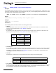

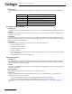


Table Of Contents
- Dialogic® DSI SS7MD Network Interface Board Programmer's Manual
- Contents
- Chapter 1: Introduction
- Chapter 2: Specification
- Chapter 3: Installation
- Chapter 4: Dialogic® DSI SS7MD Board Configuration and Operation
- 4.1 Regulatory and Geographic Considerations
- 4.2 System Structure
- 4.3 Running Host Binaries With Dialogic® DSI SS7MD Board
- 4.4 System Configuration
- 4.5 Protocol Configuration
- 4.6 Monitoring
- 4.7 ATM Monitoring
- 4.8 Switching Timeslots between LIUs
- 4.9 Received Message Timestamping
- 4.10 High Speed Link Operation
- 4.11 Operation of the Thermal Sensor
- Chapter 5: Program Execution
- Chapter 6: Message Reference
- Chapter 7: Configuration Command Reference
- 7.1 Physical Interface Configuration Commands
- 7.2 Monitor Configuration Commands
- 7.3 MTP Configuration Commands
- 7.4 ATM Configuration Commands
- 7.5 ISUP Configuration Commands
- 7.6 TUP Configuration Commands
- 7.7 SCCP Configuration Commands
- 7.8 DTC Configuration Commands
- 7.9 TCAP Configuration Commands
- 7.10 MAP Configuration Commands
- 7.11 INAP Configuration Commands
- 7.12 IS41 Configuration Commands
- Chapter 8: Host Utilities
- Appendix A: Protocol Configuration Using Discrete Messages
- Appendix B: Thermal guidelines for selecting suitable servers for use with a Dialogic® DSI SS7MDL4 Network Interface Board
- Glossary
- Index

129
Dialogic
®
DSI SS7MD Programmer’s Manual Issue 3
7.3 MTP Configuration Commands
The Message Transfer Part (MTP) configuration commands are:
• MTP_CONFIG - Configure MTP
• MTP_LINKSET - Configure a Linkset
• MTP_LINK - Configure a Link
• MTP_ROUTE - Configure a Route
• MTP_USER_PART - Configure a Local User Part
7.3.1 MTP_CONFIG – Configure MTP
Synopsis
The global configuration parameters for the Message Transfer Part (MTP).
Syntax
MTP_CONFIG <reserved1> <reserved2> <options>
Example
MTP_CONFIG 0 0 0x00040000
Parameters
MTP_CONFIG
Parameters
The MTP_CONFIG command includes the following parameters:
• <reserved1>, <reserved2>
These parameters are reserved for backwards compatibility only. For applications conforming to this
release, these parameters should always be set to 0.
• <options>
A 32-bit value containing run-time options for the operation of MTP as follows:
— Bit 0 is set to 1 to disable the MTP3 message discrimination function (allowing the signaling point to
receive all messages irrespective of the destination point code contained in the message) or 0 to
allow the discrimination function to operate normally.
— Bit 1 is set to 1 to disable sub-service field (SSF) discrimination. If this bit is set to 0, each received
MSU with an ssf value that does not match the configured ssf value for that link set is discarded.
— Bit 3 is set to 1 to cause MTP3 to generate a User Part Unavailable (UPU) message to the network on
receipt of a message containing a Service Indicator (SI) value that has not been configured. If set to
0, the message will be discarded without sending the UPU message.
— Bit 8 is set to 1 to select ANSI operation; otherwise it should be set to 0.
— Bits 9 and 20 are used to select the point codes used in the MTP routing label as defined below:
— Bit 10 is set to 1 for ANSI operation; otherwise it should be set to 0.
— Bit 11 is set to 1 for ANSI operation; otherwise it should be set to 0.
— Bit 18 is used to control MTP functionality in the event of detection of Remote Processor Outage
(RPO). If set to 1, RPO is handled in accordance with the ITU-T 1992 (and later) recommendations. If
Bit 9 Bit 20 Point Code Description
00
14-bit
ITU
01
16-bit Japan
1x
24-bit ANSI
X = indicates do not care