
Network Card User Manual
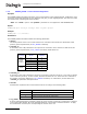

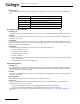


Table Of Contents
- Dialogic® DSI SS7MD Network Interface Board Programmer's Manual
- Contents
- Chapter 1: Introduction
- Chapter 2: Specification
- Chapter 3: Installation
- Chapter 4: Dialogic® DSI SS7MD Board Configuration and Operation
- 4.1 Regulatory and Geographic Considerations
- 4.2 System Structure
- 4.3 Running Host Binaries With Dialogic® DSI SS7MD Board
- 4.4 System Configuration
- 4.5 Protocol Configuration
- 4.6 Monitoring
- 4.7 ATM Monitoring
- 4.8 Switching Timeslots between LIUs
- 4.9 Received Message Timestamping
- 4.10 High Speed Link Operation
- 4.11 Operation of the Thermal Sensor
- Chapter 5: Program Execution
- Chapter 6: Message Reference
- Chapter 7: Configuration Command Reference
- 7.1 Physical Interface Configuration Commands
- 7.2 Monitor Configuration Commands
- 7.3 MTP Configuration Commands
- 7.4 ATM Configuration Commands
- 7.5 ISUP Configuration Commands
- 7.6 TUP Configuration Commands
- 7.7 SCCP Configuration Commands
- 7.8 DTC Configuration Commands
- 7.9 TCAP Configuration Commands
- 7.10 MAP Configuration Commands
- 7.11 INAP Configuration Commands
- 7.12 IS41 Configuration Commands
- Chapter 8: Host Utilities
- Appendix A: Protocol Configuration Using Discrete Messages
- Appendix B: Thermal guidelines for selecting suitable servers for use with a Dialogic® DSI SS7MDL4 Network Interface Board
- Glossary
- Index

125
Dialogic
®
DSI SS7MD Programmer’s Manual Issue 3
— E1 interfaces have 32 timeslots numbered 0 to 31. Timeslot 0 is used for frame alignment and
timeslot 16 is generally used for signaling or is empty. Hence the normal configuration is to cross
connect timeslots 1 to 15 and 17 to 31 between the two ports on each signaling board by setting the
<ts_mask> value to 0xfffefffe.
— T1/J1 interfaces have 24 timeslots, numbered 1 to 24. To cross connect all the timeslots on a T1
interface between the two PCM ports on a signaling board, the <ts_mask> value 0x1fffffe should be
used.
In duplex mode both PCM ports should have been previously configured under the same type of PCM
connector T1, E1 or J1.
• <pattern>
For DSI SS7MD Boards, not applicable. Set to 0.