
Network Card User Manual
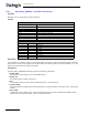
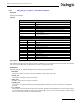
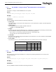
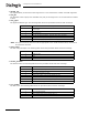
Table Of Contents
- Dialogic® DSI SS7MD Network Interface Board Programmer's Manual
- Contents
- Chapter 1: Introduction
- Chapter 2: Specification
- Chapter 3: Installation
- Chapter 4: Dialogic® DSI SS7MD Board Configuration and Operation
- 4.1 Regulatory and Geographic Considerations
- 4.2 System Structure
- 4.3 Running Host Binaries With Dialogic® DSI SS7MD Board
- 4.4 System Configuration
- 4.5 Protocol Configuration
- 4.6 Monitoring
- 4.7 ATM Monitoring
- 4.8 Switching Timeslots between LIUs
- 4.9 Received Message Timestamping
- 4.10 High Speed Link Operation
- 4.11 Operation of the Thermal Sensor
- Chapter 5: Program Execution
- Chapter 6: Message Reference
- Chapter 7: Configuration Command Reference
- 7.1 Physical Interface Configuration Commands
- 7.2 Monitor Configuration Commands
- 7.3 MTP Configuration Commands
- 7.4 ATM Configuration Commands
- 7.5 ISUP Configuration Commands
- 7.6 TUP Configuration Commands
- 7.7 SCCP Configuration Commands
- 7.8 DTC Configuration Commands
- 7.9 TCAP Configuration Commands
- 7.10 MAP Configuration Commands
- 7.11 INAP Configuration Commands
- 7.12 IS41 Configuration Commands
- Chapter 8: Host Utilities
- Appendix A: Protocol Configuration Using Discrete Messages
- Appendix B: Thermal guidelines for selecting suitable servers for use with a Dialogic® DSI SS7MDL4 Network Interface Board
- Glossary
- Index
120
7 Configuration Command Reference
• <board_id>
The logical identity of the board in the range from 0 to one less than the number of boards supported.
• <liu_id>
The identifier of the T1/E1/J1 Line Interface Unit (LIU) in the range from 0 to one less than the number
of LIUs.
• <liu_type>
The physical interface type. The following table shows the permitted values and their meanings.
Note: The option chosen by the user must be appropriate to the actual hardware fitted, otherwise an
error status is returned.
• <line_code>
The line coding technique. The following table shows the permitted values and their meanings.
• <frame_format>
The frame format. The following table shows the permitted values and their meanings.
• <crc_mode>
The CRC mode. The following table shows the permitted values and their meanings.
Value Description
1
Disabled (used to deactivate an LIU). In this mode the LIU does not produce an
output signal.
3 E1 120 ohm balanced interface
4 T1 (including J1)
5 E1 120 ohm balanced interface (preferred setting for E1 operation)
6 E1 high-impedance (for monitoring applications)
7 T1 (including J1) high-impedance (for monitoring applications)
Value Description
1 HDB3 (E1 only)
2AMI
4 B8ZS (T1/J1)
Value Description
1 E1 double frame (E1 only)
2 E1 CRC4 multiframe (E1 only)
3 F4 4-frame multi-frame (T1 only)
4 D3/D4 (Yellow alarm = bit 2 in each channel (T1 only)
7 ESF (Yellow alarm in data link channel (T1 only)
8 F72/SLC96 (72-frame multi-frame) (T1 only)
9 J1 frame format (liu_type must be T1)
Value Description
1 CRC generation disabled
2 CRC4 enabled (frame_format must be set to 2)
4 CRC6 enabled (frame_format must be set to 7)