
Network Card User Manual
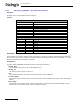
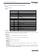
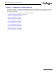
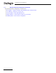
Table Of Contents
- Dialogic® DSI SS7MD Network Interface Board Programmer's Manual
- Contents
- Chapter 1: Introduction
- Chapter 2: Specification
- Chapter 3: Installation
- Chapter 4: Dialogic® DSI SS7MD Board Configuration and Operation
- 4.1 Regulatory and Geographic Considerations
- 4.2 System Structure
- 4.3 Running Host Binaries With Dialogic® DSI SS7MD Board
- 4.4 System Configuration
- 4.5 Protocol Configuration
- 4.6 Monitoring
- 4.7 ATM Monitoring
- 4.8 Switching Timeslots between LIUs
- 4.9 Received Message Timestamping
- 4.10 High Speed Link Operation
- 4.11 Operation of the Thermal Sensor
- Chapter 5: Program Execution
- Chapter 6: Message Reference
- Chapter 7: Configuration Command Reference
- 7.1 Physical Interface Configuration Commands
- 7.2 Monitor Configuration Commands
- 7.3 MTP Configuration Commands
- 7.4 ATM Configuration Commands
- 7.5 ISUP Configuration Commands
- 7.6 TUP Configuration Commands
- 7.7 SCCP Configuration Commands
- 7.8 DTC Configuration Commands
- 7.9 TCAP Configuration Commands
- 7.10 MAP Configuration Commands
- 7.11 INAP Configuration Commands
- 7.12 IS41 Configuration Commands
- Chapter 8: Host Utilities
- Appendix A: Protocol Configuration Using Discrete Messages
- Appendix B: Thermal guidelines for selecting suitable servers for use with a Dialogic® DSI SS7MDL4 Network Interface Board
- Glossary
- Index
119
Dialogic
®
DSI SS7MD Programmer’s Manual Issue 3
7.1.1 SS7_BOARD – Configure Dialogic
®
DSI SS7MD Network Interface Board
Synopsis
Command to configure a DSI SS7MD Board in the system.
Syntax
SS7_BOARD <board_id> <board_type> <flags> <code_file> <run_mode>
Example
SS7_BOARD 0 SS7MD 0x0000 ss7.dc6 LSL
Parameters
The SS7_BOARD command includes the following parameters:
• <board_id>
The logical identity of the board in the range from 0 to one less than the number of boards supported
(typically, 0 to 3).
• <board_type>
The board type within the system. Possible values are:
—SS7MD – for DSI SS7MD Boards
• <flags>
A 16-bit value that provides additional level 1 configuration for the board. The meaning of each bit may
vary with different board types. The bits have the following significance:
— Bit 0 is set to 1 to recover the clock from the LIU; 0 use internal clock
— All other bits are reserved and should be set to 0.
• <code file>
The name of the codefile that gets downloaded to the board when it is reset. Codefiles for DSI SS7MD
Boards use the suffix .dc6.
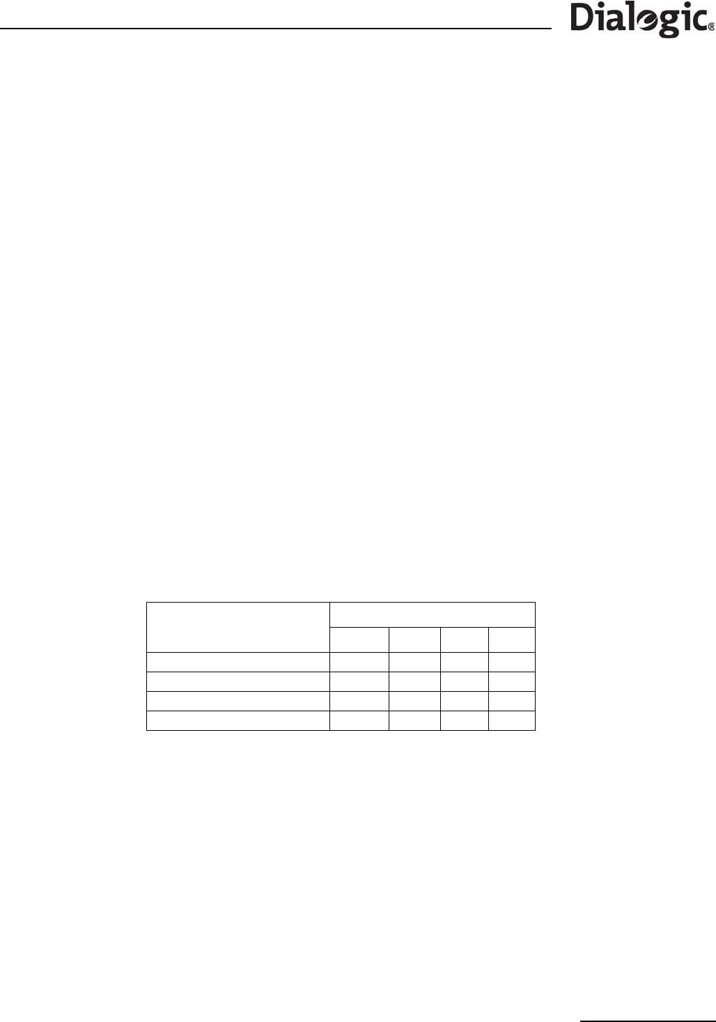
• <run_mode>
The protocols to be run. The following table shows the permitted values and their meanings.
7.1.2 LIU_CONFIG – Configure a T1/E1/J1 LIU
Synopsis
This command is used during initialization to configure the operating parameters for a T1/E1/J1 Line
Interface Unit (LIU).
Syntax
LIU_CONFIG <board_id> <liu_id> <liu_type> <line_code> <frame_format> <crc_mode> [<build_out>]
Example
LIU_CONFIG 0 051110
Parameters
The LIU_CONFIG command includes the following parameters:
Feature
<run mode>
LSL HSL ATM IMA
Low Speed Links xxx
High Speed Links xxx
ATM links xxx
Multiple ATM links in IMA bundles xx