
Network Card User Manual
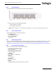
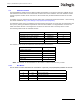
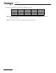


Table Of Contents
- Dialogic® DSI SS7MD Network Interface Board Programmer's Manual
- Contents
- Chapter 1: Introduction
- Chapter 2: Specification
- Chapter 3: Installation
- Chapter 4: Dialogic® DSI SS7MD Board Configuration and Operation
- 4.1 Regulatory and Geographic Considerations
- 4.2 System Structure
- 4.3 Running Host Binaries With Dialogic® DSI SS7MD Board
- 4.4 System Configuration
- 4.5 Protocol Configuration
- 4.6 Monitoring
- 4.7 ATM Monitoring
- 4.8 Switching Timeslots between LIUs
- 4.9 Received Message Timestamping
- 4.10 High Speed Link Operation
- 4.11 Operation of the Thermal Sensor
- Chapter 5: Program Execution
- Chapter 6: Message Reference
- Chapter 7: Configuration Command Reference
- 7.1 Physical Interface Configuration Commands
- 7.2 Monitor Configuration Commands
- 7.3 MTP Configuration Commands
- 7.4 ATM Configuration Commands
- 7.5 ISUP Configuration Commands
- 7.6 TUP Configuration Commands
- 7.7 SCCP Configuration Commands
- 7.8 DTC Configuration Commands
- 7.9 TCAP Configuration Commands
- 7.10 MAP Configuration Commands
- 7.11 INAP Configuration Commands
- 7.12 IS41 Configuration Commands
- Chapter 8: Host Utilities
- Appendix A: Protocol Configuration Using Discrete Messages
- Appendix B: Thermal guidelines for selecting suitable servers for use with a Dialogic® DSI SS7MDL4 Network Interface Board
- Glossary
- Index

11
Dialogic
®
DSI SS7MD Programmer’s Manual Issue 3
2.2 Dialogic
®
DSI SS7MDL4 Network Interface Board - Low Profile PCI Express Form
Factor
The DSI SS7MDL4 board is a x1 lane electrical, x4 lane physical, low profile PCI Express form factor, which
can be installed in x4, x8, or x16 lane slots. The board is supplied with two End Brackets suitable for low
profile and full height installation. Features of the DSI SS7MDL4 board are described in the following topics:
• Capacity
• Host Interface
• Physical Interfaces
• Protocol Resource Support
• Visual Indicators
• Power Requirements
• Environmental Specification
• Safety, EMC and Telecommunications Specifications
• Reliability
2.2.1 Capacity
The capacity of the DSI SS7MDL4 board is described as follows:
• Digital interfaces
— Four T1/E1 or J1 (software selectable)
— High impedance software selectable
• SS7 links
Terminate or monitor up to
Note: In order to monitor both directions of a signaling link, the user must separately connect each
direction of the signaling link to the receive connection of two different LIUs on the DSI SS7MDL4
board.
• Dialogic
®
DSI Protocol Stacks
MTP2 on board; other
protocols are host-based
2.2.2 Host Interface
The DSI SS7MDL4 board has a x1 electrical, x4 physical PCI Express connector. It can be installed in x4, x8,
or x16 PCI Express slots.
Note: The DSI SS7MDL4 board is a high performance densely packed low profile PCIe board supporting
high message rates. In achieving this performance, the board may dissipate up to 17W and this
must be taken into consideration when selecting both the host chassis and the PCI Express slot in
Table 1. SS7 Link Termination or Monitoring Capacity of the Dialogic® DSI SS7MDL4 Network
Interface Board
Link type Max. number of links per board
Q.703 LSL (64kbit/s) 124
Q.703 LSL (56kbit/s) 123
Q.703 LSL (48kbit/s) 123
Q.703 Annex A HSL Framed 4
Q.2140/Q.2110 Q.SAAL links
(terminated)
128
AAL5 (including Q.SAAL) links
(monitored)
128
ATM cell streams 4