
Specifications


Dialogic
®
DSI SS7HD Network Interface Boards Programmer's Manual Issue 11
61
Set to 3 when using an SS7HD board. A separate link layer configuration message
should be sent for each link using the MGT_MSG_L1_CONFIG message.
Note: For backwards compatibility reasons, config_type can also be set to 2, but only
when using four links or less.
flags
Global flags with the following bit significance:
— Bit 15 is set to 1 for diagnostic purposes to cause the results of board
configuration to be passed to the host. When set, all confirmation
messages generated internally on the board during the configuration
sequence are sent to the 0xdf module_id on the host.
— All other bits are reserved for future use and should be set to 0.
l1_flags
— Level 1 flags with the following bit significance:
— Bit 0 controls the reference source used for on-board clocks when acting
as CT Bus Primary Master. If set to 1, the clock is recovered from one of
the line interfaces. If set to 0, the on-board clock oscillator is used.
— Bit 3 is set to 1 to enable H.100 bus termination for SS7HDP PCI and
SS7HDE PCI Express boards. Set to 0 to disable H.100 bus termination.
Setting bus termination prevents the bus clock signal being reflected and
must be set for any board at either end of the H.100 bus. For SS7HDC
CompactPCI boards, set to 0.
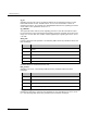
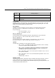
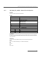
— Bit 6 and 7 together select the initial CT Bus clocking mode. The clocking
mode can subsequently be modified dynamically using the
MVD_MSG_CNFCLOCK message. The following table shows the permitted
values and their meanings.
Bit 7
Bit 6
CT Bus Clocking Mode
0
0
CT Bus interface disabled
In this mode the board is electrically isolated from the other boards using
the CT Bus. The CT Bus connection commands may still be used, but the
connections made are only visible to this board. When using this mode, the
on-board clocks are synchronized to the source selected by bit 0 of this
flags parameter.
0
1
Primary Master, A Channel
The board drives CT Bus clock set A using the clock source selected by bit
0 of this flags parameter.
1
0
Secondary Master, B Channel
The board is configured to drive clock set B in Secondary Master mode. It
automatically switches to become Primary Master if the board driving clock
set A fails. While acting as Secondary Master, the on-board clocks is
synchronized to the CT Bus clock set A.
1
1
Slave, initially A Channel
The board uses the CT Bus clocks that must be generated by another
board on the CT Bus. Initially, the board recovers from clock set A, but will
automatically switch over to recover from clock set B should set A fail.