
Specifications

Dialogic
®
DSI SS7HD Network Interface Boards Programmer's Manual Issue 11
35
3.4.1 Termination of the CT Bus
Dialogic
®
DSI SS7HDP Network Interface Boards - PCI Form Factor Products and
Dialogic
®
DSI SS7HDE Network Interface Boards - PCI Express Form Factor Products
must have their CT Bus termination parameter configured according to their position
on the CT Bus cable. The connectors at the two ends of the CT Bus cable must not be
left disconnected. For a DSI SS7HDP PCI board or a DSI SS7HDE PCI Express board
that is connected to an end connector on the CT Bus cable, it must be configured to
terminate the CT Bus. For a DSI SS7HDP PCI board or a DSI SS7HDE PCI Express
board connected to a mid connector on the CT Bus cable, or not connected at all, it
must be configured to not terminate the CT Bus. This can be achieved using the
SS7_BOARD command (Dialogic
®
Distributed Signaling Interface Components -
Software Environment Programmer's Manual, bit 3 in the flags parameter), the
MGT_MSG_CONFIG0 message (Section 4.2.4, “MGT_MSG_CONFIG0 - Board
Configuration Request” on page 60, bit 3 in the ll_flags parameter) or the
MVD_MSG_CNFCLOCK message (Section 4.3.11, “MVD_MSG_CNFCLOCK - Configure
Clock Request” on page 88, clk_term parameter).
3.4.2 Switching Model
The basic switching model assumes that at system initialization all incoming T1/E1/J1
timeslots and all resource board output timeslots are connected to channels on the CT
Bus and that these connections are never changed. This scheme has the advantage
that once the on-board CT Bus drivers have been set up, they are never changed
reducing the chances of inadvertently causing CT Bus conflict. It also means that the
user can predict the exact CT Bus channels where any input timeslot can be located,
which in turn can assist with fault diagnosis and general system test.
It is also possible to generate fixed patterns on any T1/E1/J1 output timeslots to
provide the correct Idle pattern for presentation to the network on all circuits where
there is no active call.
Having completed system initialization, all drives to the CT Bus are set up. Then, on a
dynamic (call-by-call) basis, the connectivity must be modified when a new call arrives
and when it finishes.
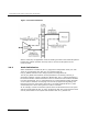
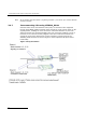
When a new call arrives, typically the application will need to initiate two listen
commands as follows:
• One command causes the resource to listen to the appropriate CT Bus channel to
hear the incoming voice path.
• The other command causes the T1/E1/J1 interface to listen to the output from
the resource board to generate the outgoing voice path
Figure 1shows the function of the commands.