
Specifications

Dialogic
®
DSI SS7HD Network Interface Boards Programmer's Manual Issue 11
19
2.3.5 Protocol Resource Support
When used in a signaling node, the DSI SS7HDC boards support the Message Transfer
Part (MTP) running on the board and optionally other protocols including ISUP, TUP,
SCCP, TCAP, MAP, INAP and IS41 running on the board or the host. The protocols are
enabled by a range of license buttons engraved with the codes BC, BD, BE and BF. See
Section 2.5, “License Buttons” on page 27.
DSI SS7HDC boards support passive monitoring of HDLC format data links including,
for example, SS7, LAPB, LAPD, ISDN and DPNSS. In this mode, the received messages
are directly reported to the application. For more information on link monitoring, see
Section 3.3, “Monitoring” on page 33.
It is possible to use monitor and receive-transmit protocol operations concurrently on
the same signaling board.
2.3.6 Visual Indicators
The DSI SS7HDC boards include the following visual indicators:
• Power On indicator (Green)
• Four General Purpose LEDs (CR1, CR2, CR3 and CR4) for use by application
developers (see Section 4.3.13, “MVD_MSG_LED_CTRL - LED Control Request”
on page 93 for more information)
• Port Status indicators (4 for each T1/E1/J1 port, see Section 2.3.6.1 following)
• Hotswap indicator (Blue)
The companion Rear Transition Modules (RTMs) include the following visual indicators:
• Two LEDs that are integrated into each Ethernet RJ-45 port:
— Ethernet Port Integrity (Green)
— Ethernet Port Activity (Amber)
The SS7HDCR8TEW Rear Transition Module (RTM) has the following additional visual
indicators:
• Two Ethernet Port Speed indicators (Green) that indicate the mode in which the
port operates, 100BaseT (On) or 10BaseT (Off).
Note: The 10/100Base-TX Ethernet interface is currently not supported.
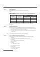
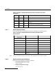
2.3.6.1 Port Status Indicators
The DSI SS7HDC boards include a set of four LEDs for each T1/E1/J1 port that provide
a status indication for the respective port. The red Loopback LED when lit indicates
that the respective trunk is in loopback mode. The green, yellow and red LEDs indicate
normal operation or Carrier Failure Alarms (CFAs) as indicated in the following table.