Dialogic® DSI SPCI Network Interface Boards Programmer's Manual March 2009 U03HSP www.dialogic.
Copyright and Legal Notice Copyright © 1993-2009 Dialogic Corporation. All Rights Reserved. You may not reproduce this document in whole or in part without permission in writing from Dialogic Corporation at the address provided below. All contents of this document are furnished for informational use only and are subject to change without notice and do not represent a commitment on the part of Dialogic Corporation or its subsidiaries (“Dialogic”).
Dialogic® DSI SPCI Network Interface Boards Programmer's Manual Issue 5 Contents Revision History ........................................................................................................... 6 1 Introduction ........................................................................................................ 7 1.1 Related Documentation............................................................................................................ 7 2 Specification.........................
Contents 5.4 Developing a User Application ................................................................................................ 34 6 Message Reference ............................................................................................ 36 6.1 Overview ............................................................................................................................. 36 6.1.1 General Configuration Messages ....................................................................
Dialogic® DSI SPCI Network Interface Boards Programmer's Manual Issue 5 8 Host Utilities ................................................................................................... 108 8.1 ssds .................................................................................................................................. 108 8.1.1 Description ........................................................................................................ 108 8.1.2 Syntax ...............................
Revision History Revision History Issue Date Description A 12-Apr-00 Initial release for evaluation purposes. Some sections incomplete. B 20-Apr-00 Several minor corrections especially relating to LIU configuration and ® switching. Addition of installation section for Windows NT. 1 30-Jul-01 Sections detailing support for Windows 2000, Linux and Solaris added. Additional messages to read LIU state, indicate clock events and s7_mgt completion status.
Dialogic® DSI SPCI Network Interface Boards Programmer's Manual Issue 5 1 Introduction The range of Dialogic® DSI SPCI Network Interface Boards includes specialized T1/E1 SS7 signaling boards for use in PCI host computer systems. All boards offer a common interface to the application allowing applications to be easily ported between hardware architectures. This Programmer’s Manual relates to the low density Dialogic® DSI SPCI4 Network Interface Boards and Dialogic® DSI SPCI2S Network Interface Boards.
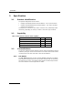
2 Specification 2 Specification 2.1 Product Identification The product designations are as follows: • Dialogic® DSI SPCI4 Network Interface Boards – Four T1/E1 interfaces • Dialogic® DSI SPCI2S Network Interface Boards – Two T1/E1 interfaces and two serial interfaces Throughout this manual the term "SPCI" is used to refer (individually and/or collectively, depending on context) to either or both such type of boards. 2.2 Capability Table 1: SPCI Network Interface Board Capability 2.
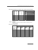
Dialogic® DSI SPCI Network Interface Boards Programmer's Manual Issue 5 2.3.2 √ MM SS7SBPCIMONQ Monitoring 4 M3 SS7SBPCIMTPQ MTP 4 √ √ T1 SS7SBPCIISTUPSQ ISUP, TUP (Small) 2 √ √ T2 SS7SBPCIISTUPQ ISUP, TUP (Regular) 4 √ √ T4 SS7SBPCIISTUPLQ ISUP, TUP (Large) 4 √ √ √ √ √ √ √ √ √ √ √ Capacity The figures in the table below indicate the capacity for modules running on the DSI SPCI Boards.
3 Installation 3 Installation 3.1 Introduction This Programmer's Manual covers the installation and use of the software contained in the following distributions: • Development Package for Windows® • Development Package for Linux • Development Package for Solaris • User Part Development Package • Code Files for Dialogic® DSI SPCI Network Interface Boards (various protocols).
Dialogic® DSI SPCI Network Interface Boards Programmer's Manual Issue 5 3.2 3.2.1 Hardware configuration Board Option Switch / Link Settings The DSI SPCI Boards contain some switches and links used to establish optional settings at the time of installation in a host. These must be set as follows: 3.3 • CT Bus termination links - full details of how to use these links is provided in the relevant board Installation Guide.
3 Installation Table 4: Files Installed on a System Running Windows® Name gctlib.lib Description Library to be linked with user's application (Microsoft*). gctlibb.lib Library to be linked with user's application (Borland*). INC Sub-directory containing include files. system.txt Example system configuration file. config.txt Example protocol configuration file. gctload.exe ssds.exe s7_mgt.exe s7_log.exe s7_play.exe tick_nt.exe tim_nt.exe servcfg.exe gctserv.exe mtpsl.exe upe.
Dialogic® DSI SPCI Network Interface Boards Programmer's Manual Issue 5 Net start Septel After rebooting the interface will be displayed as expected. 4) Right click on the "Septel" driver and select "Properties" and then select the "Driver" tab. 5) The driver can be started immediately by selecting "start" in the "current status" field. Note: To automatically start the driver at system startup, select the "Automatic" option from the "Startup" menu.
3 Installation 3.3.4 Removing Development Package for Windows® Prior to installing a new version of the Development Package for Windows®, the previous package must be removed as follows. This procedure requires a user with Administrator privilege. 1) Select the Control Panel (Start Æ Settings Æ Control Panel). 2) Select "Add/Remove Programs". 3) Scroll down the devices and select "SS7 Development Package" and select "Remove". 4) When package removal is confirmed, restart the target machine. 3.
Dialogic® DSI SPCI Network Interface Boards Programmer's Manual Issue 5 Table 5: Files Installed on a System Running Linux Name gctlib.lib Description Library to be linked with user's application. system.txt Example system configuration file. config.txt Example protocol configuration file. gctload.exe ssds.exe s7_mgt.exe s7_log.exe s7_play.exe tick_nt.exe tim_nt.exe upe.exe Executables for use as described elsewhere in this manual.
3 Installation This warning can be safely ignored. For compatibility with the pre-built drivers the existing name format is retained for Linux 2.4 drivers e.g., sptcpi-2.4.18-14smp.o. However, this name format causes problems under Linux Kernel version 2.6; therefore, all Linux 2.6 drivers are named sptpci26.ko. An install script, named install_spci_cpm.sh, is included in the package.
Dialogic® DSI SPCI Network Interface Boards Programmer's Manual Issue 5 On successful completion of the installation procedure, the following message is displayed, and the user needs to reboot the system. Installation of DKseptel was successful. The following files (or similar) are transferred into the /opt/DKseptel directory. Note: Additional files relating to other products in the range are installed at the same time. Table 6: Files Installed on a System Running Solaris Name 3.5.
3 Installation To enable this functionality the following line must be added to the /etc/system file: set sptpci:spt_claimint=1 The system has to be rebooted to force the change to take effect. 3.5.5 Removing the Development Package for Solaris The Development Package for Solaris is removed using the package removal utility: pkgrm The Solaris package removal utility (pkgrm) then prompts for further input.
Dialogic® DSI SPCI Network Interface Boards Programmer's Manual Issue 5 4 Configuration and Operation 4.1 Overview Prior to performing software configuration, the user should gain an appreciation of: • the flexibility of the protocol stack, • the run-time options that exist, • the mechanisms used to select particular features. This section gives an overview of these aspects.
4 Configuration and Operation The following abbreviations are used in the table: MTP2 Message Transfer Part – Level 2 MTP3 Message Transfer Part – Level 3 ISUP ISDN User Part TUP Telephony User Part In all cases, the process called ssds (SS7 Software Driver) must be run on the host computer. This handles message transfer between the host and the board using the device driver. To define which protocol modules run on the host, edit the text file system.txt.
Dialogic® DSI SPCI Network Interface Boards Programmer's Manual Issue 5 4.2 System Configuration System configuration is handled by the program gctload, which reads the system configuration data from a file called system.txt. This file must be edited to reflect the requirements of your system, prior to running gctload. System initialization requires first that a pool of message buffers is created for subsequent inter-process communication.
4 Configuration and Operation The full syntax of each command is listed in the Software Environment Programmer’s Manual. An example system.txt file is shown below: * * Example system.txt for the Development Package for Windows®. * * Edit this file to reflect your configuration.
Dialogic® DSI SPCI Network Interface Boards Programmer's Manual Issue 5 LOCAL LOCAL LOCAL 0xcf 0x2d 0x3d * s7_mgt - Management/config task * upe - Example user part task * s7_log - Prints messages to screen/file After the LOCAL declarations, REDIRECT commands are added for modules that run on the board so that messages destined for these modules are transported via ssds (module_id = 0x20) and the device driver, to the board.
4 Configuration and Operation 4.3 Protocol Configuration The Development Package contains a protocol configuration utility, s7_mgt which performs initialization of all the software modules running on the signaling board. It reads the protocol configuration data from a text file called config.txt and provides a quick and flexible method of configuring the protocol modules without the need to write software for that purpose.
Dialogic® DSI SPCI Network Interface Boards Programmer's Manual Issue 5 To configure the board using individual messages, the following sequence must be used. (The format of all the messages is described in Section 5 of this manual): 1) Build and send an SSD Reset Message. This contains the parameters to initialize the ssds module. 2) Build and send a Board Reset Message for each board. This includes the id of the board and the name of the Code File.
4 Configuration and Operation 4.4 Board Information Diagnostics To assist in diagnosis of configuration problems and reporting hardware details when encountering problems, a diagnostic display feature is available in s7_mgt. When s7_mgt is run with the –d command line option, a diagnostic display of board hardware parameters is generated in this format following configuration of the board.
Dialogic® DSI SPCI Network Interface Boards Programmer's Manual Issue 5 4.5 Geographic Addressing Geographic Addressing allows the logical position of a board (or board_id) in a system to remain the same irrespective of the addition or removal of other boards on the PCI bus. Two address modes are supported: • PCI address mode – (default) addressing determined by enumerating boards on the PCI bus at boot time (i.e., the default order found by the operating system).
4 Configuration and Operation 4.7.1 Switching Model The basic switching model assumes that at system initialization all incoming T1/E1 timeslots and all resource board output timeslots are connected up to channels on the CT bus and that these connections are never changed. This has the advantage that once the on-board CT bus drivers have been set up they are never changed so the chances of inadvertently causing CT bus conflict is minimized.
Dialogic® DSI SPCI Network Interface Boards Programmer's Manual Issue 5 LIU_SC_DRIVE 17..31 LIU_SC_DRIVE 17..31 LIU_SC_DRIVE 17..31 LIU_SC_DRIVE 17..31 LIU_SC_DRIVE 1..23 LIU_SC_DRIVE 1..23 LIU_SC_DRIVE 1..23 LIU_SC_DRIVE 1..23 4.7.3 0 0 512 0xfffefffe * 30 E1 voice ccts on ts 1..15 & 0 1 542 0xfffefffe * 30 E1 voice ccts on ts 1..15 & 0 2 572 0xfffefffe * 30 E1 voice ccts on ts 1..15 & 0 3 602 0xfffefffe * 30 E1 voice ccts on ts 1..
4 Configuration and Operation #include "pack.h" /* Prototypes for rpackbytes */ #include "ss7_inc.
Dialogic® DSI SPCI Network Interface Boards Programmer's Manual Issue 5 m->hdr.src = OUR_MOD_ID; /* * Call GCT_set_instance to route the message to the * correct board and GCT_send to send the message. * If GCT_send returns non-zero release the message. */ GCT_set_instance(board_id, (HDR *)m); if (GCT_send(m->hdr.
5 Program Execution 5 Program Execution This chapter describes how to start the software running. It assumes that the software has already been installed and the configuration files system.txt and config.txt have been modified accordingly. Refer to previous sections if unsure. There are three main stages to get a new application up and running although the procedure may vary slightly depending on the operating system. 1) The device driver must be installed and running.
Dialogic® DSI SPCI Network Interface Boards Programmer's Manual Issue 5 5.2 Program Execution under Linux Ensure the device driver has been installed and the system configuration file (system.txt) has been modified according to the system requirements to select the correct protocols etc. Ensure the code file has been copied to the directory containing the SS7 binaries. If using s7_mgt, ensure the protocol configuration file config.txt has been edited to provide protocol configuration.
5 Program Execution 5.3 Program Execution under Solaris Ensure the device driver has been installed and the system configuration file (system.txt) has been modified according to the system requirements to select the correct protocols etc. Ensure the code file has been copied to the directory containing the SS7 binaries. If using s7_mgt, ensure the protocol configuration file config.txt has been edited to provide protocol configuration.
Dialogic® DSI SPCI Network Interface Boards Programmer's Manual Issue 5 gctlib.lib gctlibb.lib gctlib.lib gctlib.lib (Windows® using Microsoft compiler) (Windows® using Borland compiler) (Linux) (Solaris) Some simple example programs are supplied to illustrate the techniques for interfacing to the protocol stack although they are not intended to show a real application. Before starting to develop an application, you can familiarize yourself with the example programs and how they are built.
6 Message Reference 6 Message Reference 6.1 Overview This section describes the individual messages that may be sent to and received from the Dialogic® DSI SPCI Network Interface Board. Some messages are sent by the user's application software whilst others are sent by utility programs such as the configuration utility s7_mgt.
Dialogic® DSI SPCI Network Interface Boards Programmer's Manual Issue 5 6.1.3 MTP Interface Messages MTP Interface Messages allow signaling links to be activated and deactivated by the user and provide a mechanism for communication between the MTP3 module and the user part module (e.g., ISUP or TUP).
6 Message Reference 38 0x3e18 Confirmation of MVD_MSG_SC_DRIVE_LIU 0x3e1f Confirmation of MVD_MSG_SC_CONNECT 0x3e20 Confirmation of MVD_MSG_CNFCLOCK 0x3e21 Confirmation of MVD_MSG_CLK_PRI 0x3e34 Confirmation of LIU_MSG_CONFIG 0x3e35 Confirmation of LIU_MSG_CONTROL 0x3f10 Confirmation of MGT_MSG_CONFIG0 0x5e37 LIU_MSG_R_CONFIG LIU Read Configuration Request 0x5e38 LIU_MSG_R_CONTROL LIU Read Configuration Request 0x5e39 LIU_MSG_R_STATE LIU State Request 0x6111 GEN_MSG_MOD_IDENT Gene
Dialogic® DSI SPCI Network Interface Boards Programmer's Manual Issue 5 6.2 General Configuration Messages 6.2.1 SSD Reset Request Synopsis: Message sent to SSD once at initialization to set up run-time options. Note: When using s7_mgt, this message is generated by s7_mgt and must not be generated by the user.
6 Message Reference num_boards The maximum number of boards that ssd is required to manage. This must not exceed 16. Status Response The confirmation message (if requested) indicates success by status of zero. On error, the following value can be found in the status message confirmation. 6.2.2 Value Mnemonic Description 2 SSD_BAD_PARAM The SSD Reset Request message was incorrectly formatted.
Dialogic® DSI SPCI Network Interface Boards Programmer's Manual Issue 5 Description: This message is used during initialization (or re-configuration) by the application to reset a board and download the code file that contains the operating software for the board. The download operation is supervised by the device driver that reads the binary format code file and transfers it to the board. The confirmation message (if requested) indicates success by status of zero.
6 Message Reference Run Mode Value Run Mode Mnemonic Protocols selected to run on the board 1 DTI Digital Trunk Interface only, no protocol software. This mode does NOT require the use of a software license button. 2 MTP2 MTP2 protocol only. 3 MTP MTP3 plus MTP2 protocols. 25 ISUP-S ISUP, small version, plus all MTP. 4 ISUP ISUP, regular version, plus all MTP. 5 ISUP-L ISUP, large version, plus all MTP. 26 TUP-S TUP, small version, plus all MTP.
Dialogic® DSI SPCI Network Interface Boards Programmer's Manual Issue 5 Description Event Type This message is used to convey the status of a board reset operation (success of failure) to the user. The status is indicated in the status field of the message header. The following table shows the possible Event Type values: 6.2.
6 Message Reference PARAMETER AREA 8 2 max_sif_len 10 2 l3_flags 12 4 pc 16 2 ssf 18 2 up_enable 20 2 link0_flags 22 2 link0_slc 24 4 link0_adj_pc 28 2 link0_stream 30 2 link0_timeslot 32 2 link1_flags 34 2 link1_slc 36 4 link1_adj_pc 40 2 link1_stream 42 2 link1_timeslot 44 2 link2_flags 46 2 link2_slc 48 4 link2_adj_pc 52 2 link2_stream 54 2 link2_timeslot 56 2 link3_flags 58 2 link3_slc 60 4 link3_adj_pc 64 2 link3_stream 66 2 lin
Dialogic® DSI SPCI Network Interface Boards Programmer's Manual Issue 5 If the board is not licensed to run the requested software configuration, status value of 0xfe is returned. Parameter Description: flags - Global flags Bit 0 is set to 1 to indicate that the user does not wish to use signaling software. This allows operation of the board without a software license button providing the board is used only for T1/E1 interface and switching purposes.
6 Message Reference Bit 13 is set to 1 to cause the board to drive the CT_NETREF1 clocks on the CT bus. The highest priority in-sync line interface is used as a clock source. If this bit is set to zero then CT_NETREF1 clock is not driven. All other bits are reserved and must be set to zero. l2_flags - level 2 flags Bit 1 is set to 1 for ANSI operation or zero for ITU-T operation. Bit 3 is set to 1 for ANSI operation or zero for ITU-T operation.
Dialogic® DSI SPCI Network Interface Boards Programmer's Manual Issue 5 up_enable - User Part Enable A 16 bit mask used to enable or disable reception of messages on a per user part basis. If bit N is set to 1, then messages for user part N are received by the signaling point. For example, to enable the TUP User Part (Service indicator = 4) set the up_enable field to 0x0010, For ISUP (Service Indicator = 5), set the up_enable field to 0x0020. To use both TUP and ISUP, set up_enable to 0x0030.
6 Message Reference Bit 15 is set to 1 to disable the link, or zero to enable the link. All other bits are reserved for future use and must be set to zero. linkn_slc - Signaling link code The signaling link code for the link, which must be in the range 0 to 15. The signaling link code must be agreed with the administration at the other end of the link and must be unique within a link set. Usually, the first link in a link set is assigned the value 0, the next 1, and so on.
Dialogic® DSI SPCI Network Interface Boards Programmer's Manual Issue 5 6.2.5 General Module Identification Message Synopsis: Message used to request the module type and software revision number.
6 Message Reference text Null terminated string giving textual module identity (e.g., "SS7.DC3"). 6.2.6 Read Board Info Request Message Synopsis Message used to request basic board information. This message may be sent to several Dialogic® DSI SS7 Boards, but only the parameters relevant to the Dialogic® DSI SPCI Network Interface Boards are described below.
Dialogic® DSI SPCI Network Interface Boards Programmer's Manual Issue 5 Format MESSAGE HEADER Field Name Meaning type MGT_MSG_R_BRDINFO (0x6f0d) id 0 src Sending module_id dst MGMT_TASK_ID (0x8e) rsp_req used to request a confirmation hclass 0 status Status Response (if confirmation requested) err_info 0 len 60 PARAMETER AREA Offset Size Name 0 1 board_type 1 1 board_rev 2 1 reserved 3 1 swa 4 1 swb 5 1 reserved 6 1 reserved 7 1 reserved 8 1 prom_maj_rev 9
6 Message Reference board_rev The DSI SPCI Board hardware revision number. swa The setting of the board's rotary switch labeled "Boot". Note: The switch should be set to 8. swb Geographic addressing switch setting, that is, the address at which the board appears when the -o3 feature of ssds is used. prom_maj_rev Firmware major revision number. prom_min_rev Firmware minor revision number. esn The board's electronic serial number. lsn License serial number. The serial number of the fitted license button.
Dialogic® DSI SPCI Network Interface Boards Programmer's Manual Issue 5 6.3 Hardware Control Messages 6.3.1 LIU Configuration Request Synopsis: Message sent by the application to establish the operating mode for a Line Interface Unit (LIU). Note: When using s7_mgt, this message is generated by s7_mgt as a result of the LIU_CONFIG command. It therefore does not need be generated by the user.
6 Message Reference Description: This message is sent to the DSI SPCI Board to configure the operating mode a line interface unit. All configuration parameters must be supplied in the message (it is not possible to modify individual operating parameters in isolation). On receipt of the message the board first verifies that the fitted hardware options support the requested operating mode and then initializes (or re-initializes) the line interface unit.
Dialogic® DSI SPCI Network Interface Boards Programmer's Manual Issue 5 frame_format Description 1 E1 double frame (E1 only). 2 E1 CRC4 multiframe (E1 only). 4 D3/D4 (Yellow alarm = bit 2 in each channel) (T1 only). 7 ESF (Yellow alarm in data link channel) (T1 only). crc_mode The CRC mode taken from the following table: crc_mode Description 1 CRC generation disabled. 2 CRC4 enabled (frame_format must be set to 2). 3 CRC4 compatibility mode (frame_format must be set to 2).
6 Message Reference rai_gen The (initial) mode used to generate the Remote Alarm Indication (Yellow Alarm) taken from the following table. The user may subsequently modify the setting of the outgoing RAI alarm using the LIU_MSG_CONTROL message. rai_gen Description 1 Disabled - do not generate RAI / Yellow alarm. 2 Forced active - generate RAI / Yellow alarm. 3 Automatic generation of RAI / Yellow alarm upon loss of synchronization.
Dialogic® DSI SPCI Network Interface Boards Programmer's Manual Issue 5 6.3.2 LIU Control Request Synopsis: Message sent by the application to dynamically control operation for a Line Interface Unit (LIU). Allows setting of outgoing alarms and diagnostic loopbacks.
6 Message Reference ais_gen Description 0 Do not change AIS / Blue alarm generation mode. 1 Disabled - do not generate AIS / Blue alarm. 2 Enabled - generate AIS / Blue alarm. rai_gen The mode used to generate the Remote Alarm Indication (Yellow Alarm) taken from the following table: rai_gen Description 0 Do not change RAI / Yellow alarm generation mode. 1 Disabled - do not generate RAI / Yellow alarm. 2 Forced active - generate RAI / Yellow alarm.
Dialogic® DSI SPCI Network Interface Boards Programmer's Manual Issue 5 6.3.3 LIU Read Configuration Request Synopsis: Message sent by the application to read back the current LIU configuration from the DSI SPCI Board.
6 Message Reference 6.3.4 Value Mnemonic Description 0x01 None Invalid framer ID. 0x02 None Invalid message length. 0x03 None Control parameters are not consistent with the type of device being controlled or with each other. LIU Read Control Request Synopsis: Message sent by the application to read back the current LIU control options from the DSI SPCI Board.
Dialogic® DSI SPCI Network Interface Boards Programmer's Manual Issue 5 Status Response The confirmation message (if requested) indicates success by status of zero. On error, the following status value can be found in the confirmation message. 6.3.5 Value Mnemonic Description 0x01 None Invalid framer ID. 0xff None Invalid message length. LIU State Request Synopsis: Message sent by the application to read the current state of a Line Interface Unit (LIU).
6 Message Reference Parameter Description: state The current state of the LIU from the following table: State Description 0 OK 1 PCM Loss 2 AIS 3 Sync Loss 4 Remote Alarm Status Response The confirmation message (if requested) indicates success by status of zero. On error, the following status values can be found in the confirmation message. 6.3.6 Value Mnemonic Description 0x01 None Invalid framer ID. 0xff None Invalid message length.
Dialogic® DSI SPCI Network Interface Boards Programmer's Manual Issue 5 Message Format: MESSAGE HEADER Field Name Meaning type MVD_MSG_SC_DRIVE_LIU (0x7e18) id 0 src Sending Module ID dst MVD_TASK_ID (0x10) rsp_req used to request a confirmation hclass 0 status Status Response (if confirmation requested) err_info 0 len 10 PARAMETER AREA Offset Size Name 0 2 liu_id 2 2 sc_channel 4 4 ts_mask 8 2 mode Parameter Description: liu_id The identifier of the T1/E1 Line Interface
6 Message Reference Timeslots containing SS7 signaling processed by the signaling processor on the DSI SPCI Board should not be included in the timeslot mask. Usually, the mask should be set to include all bearer (voice) timeslots but no signaling timeslots. Bit 0 (corresponding to timeslot 0 on the LIU) must not be set as timeslot 0 for an E1 interface contains synchronization information whilst timeslot 0 for a T1 interface does not exist.
Dialogic® DSI SPCI Network Interface Boards Programmer's Manual Issue 5 6.3.7 CT bus Listen Request Synopsis: Message sent to the DSI SPCI Board to establish a connection from the CT bus to an outgoing timeslot on an T1/E1 Line Interface Unit (LIU).
6 Message Reference Parameter Description: liu_id The identifier of the T1/E1 Line Interface Unit in the range 0 to one less than the number of LIUs fitted. This parameter can also be set to the special value 0x83 to select the signaling processor instead of an LIU. In this case, timeslots 0 ... 3 correspond to signaling processor 0 ... 3 respectively. Note: For the SPCI2S, valid values for the LIU identifiers are 2 and 3.
Dialogic® DSI SPCI Network Interface Boards Programmer's Manual Issue 5 6.3.8 Fixed Data Output Request Synopsis: Message sent to the DSI SPCI Board in order to generate a fixed pattern on a specific T1/E1 Line Interface Unit timeslot.
6 Message Reference timeslot The timeslot number on the T1/E1 line interface unit on which the fixed data is transmitted. The valid range for timeslot is 1 to 31 for an E1 interface and 1 to 24 for a T1 interface. pattern The value of the fixed data to be generated. The value must be in the range 0 to 255. Typical values are 0xff for an "all ones" idle pattern, or 0x2a for an ITU-T E1 idle pattern. Status Response The confirmation message (if requested) indicates success by status of zero.
Dialogic® DSI SPCI Network Interface Boards Programmer's Manual Issue 5 Description: This message is sent to the DSI SPCI Board to reset the state of the digital cross connect switch in accordance with the configuration set using the DSI SPCI Board configuration message. All CT bus streams are tri-stated leaving just switch paths established using the board configuration message (i.e., signaling timeslots) in place. The confirmation message (if requested) indicates success by status of zero.
6 Message Reference Message Format: MESSAGE HEADER Field Name Meaning type MVD_MSG_SC_CONNECT (0x7e1f) id 0 src Sending Module ID dst MVD_TASK_ID (0x10) rsp_req used to request a confirmation hclass 0 status Status Response (if confirmation requested) err_info 0 len 16 PARAMETER AREA Offset Size Name 0 2 local_stream 2 2 local_slot 4 2 mode 6 2 source_stream 8 2 source_slot 10 2 dest_stream 12 2 dest_slot 14 2 pattern Description: This message is sent to the D
Dialogic® DSI SPCI Network Interface Boards Programmer's Manual Issue 5 Mode Required Parameters local st local ts source st source ts 1 * * * * 2 * * 3 * * 4 * * 5 * * * * 6 * * 10 * * 11 * * * * 12 * * * * dest st dest ts * * * * pattern * If a parameter is not required, it must be set to zero. local_stream The local stream defines which local stream to use for all the modes of operation.
6 Message Reference mode = 2 : Make a simplex connection from a timeslot on the local bus to a timeslot on the CT bus. Using parameters local_stream, local_slot, dest_stream and dest_slot, to specify the local and CT bus timeslots respectively. mode = 3 : Make a duplex connection between a local stream timeslot and 2 CT bus timeslots.
Dialogic® DSI SPCI Network Interface Boards Programmer's Manual Issue 5 dest_stream The destination stream references which of the CT bus streams is used as a destination for the data. The parameter takes values in the range 0…31. dest_slot The destination slot references the CT bus timeslot to which a local stream timeslot can be connected or disconnected. The destination slot value has the same range as the source slot. pattern The value of the fixed data to be generated.
6 Message Reference 6.3.11 Configure Clock Request Synopsis: Message sent to a DSI SPCI Board to configure the clocking mode for the board.
Dialogic® DSI SPCI Network Interface Boards Programmer's Manual Issue 5 Value Bus speed 0 No change 2 4.096 MHz (Reserved for future use) 3 8.
6 Message Reference The PLL clock is used as the reference when acting as CT bus Primary Master. If the clock is to be recovered from one of the line interfaces then the highest-priority in sync line interface is used as the reference. Each line interface is assigned a priority: by default liu_id=0 is the highest priority and liu_id=7 the lowest. The user may modify the priority order by sending the MVD_MSG_CLOCK_PRI message.
Dialogic® DSI SPCI Network Interface Boards Programmer's Manual Issue 5 6.3.12 Configure Clock Priority Request Synopsis: Message sent to a DSI SPCI Board to configure the clock recovery priority order.
6 Message Reference Parameter Description: liun_pri The relative priority for each LIU using the values taken from the following table: Value 0 1 … 32 255 Meaning No change to the interface’s priority. New priority value for the line interface. The value 1 indicates highest priority, 32 the lowest priority. If two interfaces are given the same priority, the lowest-numbered interface is used first. Special value indicating that the line interface must not be used for clock recovery.
Dialogic® DSI SPCI Network Interface Boards Programmer's Manual Issue 5 6.4 Event Indication Messages 6.4.1 Board Status Indication Synopsis: Message sent to the application on completion of the reset and download sequence or on detection of a board failure. Note: This message is not required when using the configuration utility s7_mgt.
6 Message Reference Parameter Description: Board Status 6.4.2 Value Mnemonic Description 0x60 SSDSI_RESET Processor successfully reset. 0x62 SSDSI_FAILURE Failure to reset board. 0x64 SSDSI_BRD_RMVD Board removed (hot swap only). 0x65 SSDSI_BRD_INS Board inserted (hot swap only). 0x66 SSDSI_LIC_FAIL License validation failure. 0x67 SSDSI_LIC_CRP License corruption. 0x70 SSDSI_BCONG_CLR Message congestion towards board cleared.
Dialogic® DSI SPCI Network Interface Boards Programmer's Manual Issue 5 Description: This message is issued by s7_mgt on completion of the initial configuration sequence and indicates either success (status=zero) or an error condition that occurred during configuration. The message is only issued when s7_mgt is run with the –i command line option specifying the module_id of the Notification Module to which the message is sent.
6 Message Reference Description: This message is issued by the board to indicate events within the on-board clocking circuitry. Parameter Description: Event ID This field specifies the event that caused the indication to be generated: event_id 82 Description 1 PLL entered hold-over mode Issued by boards acting as primary or secondary clock master when its nominated clock reference becomes unavailable.
Dialogic® DSI SPCI Network Interface Boards Programmer's Manual Issue 5 6.4.4 LIU Status Indication Synopsis: Message issued by the board to notify of changes of LIU status. Message Format: MESSAGE HEADER Field Name Meaning type MVD_MSG_LIU_STATUS (0x0e01) id liu_id src MVD_TASK_ID dst MGMT_TASK_ID rsp_req 0 hclass 0 status liu_status (see below) err_info Reserved for future use. len 0 Description: This message is issued by the board for every change of state on the trunk interface.
6 Message Reference 6.4.
Dialogic® DSI SPCI Network Interface Boards Programmer's Manual Issue 5 Parameter Description: Error Code The Error Code is coded as shown in the following table: Value Mnemonic ID Description 0x31 S7E_RESET_ERR 0x33 S7E_POOL_EMPTY l2_llid MTP2 Failed to initialize. No free buffers in MTP2 transmit pool. 0x34 S7E_TX_FAIL l2_llid Failed to send LSSU/FISU to driver. 0x35 S7E_HDR_ERR l2_llid No room to add level 2 header, SU not transmitted.
6 Message Reference 6.4.6 MTP2 Level 2 State Indication Synopsis: Indication issued by the board every time the level 2 link state control state machine changes state. Message Format: MESSAGE HEADER Field Name Meaning type MGT_MSG_SS7_STATE (0x0201) id llid (Level 2 logical link id - 0 ...
Dialogic® DSI SPCI Network Interface Boards Programmer's Manual Issue 5 6.4.7 MTP2 Q.752 Event Indication Synopsis: Message issued by MTP2 to advise management of protocol events in accordance with ITU-T Q.752.
6 Message Reference Value 88 Mnemonic Description 0 S7F_STOP Stop request received 1 S7F_FIBR_BSNR Abnormal FIBR/BSNR 2 S7F_EDA Excessive delay of acknowledgement 3 S7F_SUERM Excessive error rate (SUERM) 4 S7F_ECONG Excessive congestion 5 S7F_SIO_RXD Unexpected SIO received 6 S7F_SIN_RXD Unexpected SIN received 7 S7F_SIE_RXD Unexpected SIE received 8 S7F_SIOS_RXD SIOS received 16 S7G_CONG Onset of signaling link congestion 17 S7G_CONG_CLR Abatement of signaling link cong
Dialogic® DSI SPCI Network Interface Boards Programmer's Manual Issue 5 6.4.8 MTP3 Q.752 Event Indication Synopsis: Message issued by MTP3 to notify management of various protocol events in accordance with ITU-T Q.752.
6 Message Reference Value 90 Mnemonic Paramter Description 1 MTPEV_CO link Changeover 2 MTPEV_CB link Changeback 3 MTPEV_REST link Restoration commenced 4 MTPEV_RPO link Remote processor outage 5 MTPEV_RPO_CLR link Remote processor outage cleared 6 MTPEV_CONG link Signaling link congestion 7 MTPEV_CONG_CLR link Congestion cleared 8 MTPEV_CONG_DIS link MSU discarded due to congestion 9 MTPEV_LS_LOST linkset Link set failure 10 MTPEV_LS_OK linkset Link set recovere
Dialogic® DSI SPCI Network Interface Boards Programmer's Manual Issue 5 7 CONFIGURATION COMMAND Reference This chapter describes the commands and parameters used in the protocol configuration file config.txt. These are used by the s7_mgt utility to perform single-shot configuration of the protocol stack at startup. 7.1 7.1.1 Physical Interface Parameters SS7_BOARD Command Syntax: SS7_BOARD Example: SS7_BOARD 0 SPCI4 0x0043 ss7.
7 CONFIGURATION COMMAND Reference Bit 7 Bit 6 CT Bus Clocking Mode 0 0 The CT bus interface is disabled - In this mode, the board is electrically isolated from the other boards using the CT bus. The CT bus connection commands may still be used, but the connections made are only visible to this board. When using this mode, the on-board clocks are synchronized to the source selected by bit 0 of this flags parameter.
Dialogic® DSI SPCI Network Interface Boards Programmer's Manual Issue 5 run_mode Protocols selected to Run on the Board DTI Digital Trunk Interface only, no protocol software. This mode does NOT require the use of a software license button). MTP2 MTP2 protocol only. MTP MTP3 plus MTP2 protocols. ISUP-S ISUP, small version, plus all MTP. ISUP ISUP, regular version, plus all MTP. ISUP-L ISUP, large version, plus all MTP. TUP-S TUP, small version, plus all MTP.
7 CONFIGURATION COMMAND Reference liu_type Description 1 Disabled (used to deactivate a LIU). In this mode the LIU does not produce an output signal. 2 E1 75ohm unbalanced interface (for future use). 3 E1 120ohm balanced interface. 4 T1 5 E1 75ohm or 120ohm setting based on fitted hardware. (This is the preferred method of selecting an E1 interface). The line coding technique taken from the following table: line_code Description 1 HDB3 (E1 only).
Dialogic® DSI SPCI Network Interface Boards Programmer's Manual Issue 5 7.1.3 LIU_SC_DRIVE Command Syntax: LIU_SC_DRIVE {} Example: LIU_SC_DRIVE 0 0 512 0xfffefffe This command is used during initialization to set up a static switch path through the board between the Line Interface Unit (LIU) and the CT bus.
7 CONFIGURATION COMMAND Reference This parameter allows the user to select how the CT bus channels are allocated. Usually (mode=1) the first timeslot connected to the CT bus is connected to sc_channel and each subsequent timeslot that is selected is connected to the next CT bus channel. This allows maximum utilization of channels on the CT bus.
Dialogic® DSI SPCI Network Interface Boards Programmer's Manual Issue 5 7.2 7.2.1 MTP Parameters MTP Global Configuration Syntax: MTP_CONFIG Example: MTP_CONFIG 0 0 0x00040f00 The global configuration parameters for the Message Transfer Part (MTP). , These parameters are reserved for backwards compatibility. For applications conforming to this release of the documentation these parameters must always be set to zero.
7 CONFIGURATION COMMAND Reference Bit 21 is set to 1 for use in Japanese networks; otherwise it must be set to zero. All other bits are reserved for future use and must be set to zero. Note: 7.2.2 For ANSI operation bits 8, 9, 10, 11, and 18 must all be set to 1. MTP Link Set Syntax: MTP_LINKSET Example: MTP_LINKSET 0 321 2 0x0000 456 0x8 Configuration of a link set to an adjacent signaling point.
Dialogic® DSI SPCI Network Interface Boards Programmer's Manual Issue 5 The link’s unique logical link identity. It must be in the range 0 to one less than the total number of signaling links supported. The logical identity of the link set to which the link belongs. The linkset must already have been configured using the MTP_LINKSET command. The logical identity within the link set of the signaling link.
7 CONFIGURATION COMMAND Reference Bit 2 is set to 1 to cause a signaling link test (in accordance with ITU-T Q.707 / ANSI T1.111.7) to be carried out every 30 seconds. Note that this bit is ignored unless bit 1 is also set to 1. Bit 8 is used to select the MTP2 error correction mode. It is set to 1 to select PCR (Preventive Cyclic Retransmission) operation or zero for the Basic Method of Error Correction. Bit 11 is set to 1 to select 56kbit/s operation for the link or zero for 64kbit/s operation.
Dialogic® DSI SPCI Network Interface Boards Programmer's Manual Issue 5 a) The only link set used to reach the destination. b) The preferred link set used to reach the destination. c) One of a pair of links sets forming a combined link set. In the latter two cases a second link set (second_ls) must also be specified. Within a link set messages are automatically load-shared across links using the Signaling Link Selection (SLS) field in the message.
7 CONFIGURATION COMMAND Reference 7.2.5 MTP User Part Syntax: MTP_USER_PART Example: MTP_USER_PART 0x0a 0x2d Configuration of a local user part module (other than a user part which has its own config command in config.txt). The service indicator. The module id of the user process. Note: 7.3 7.3.
Dialogic® DSI SPCI Network Interface Boards Programmer's Manual Issue 5 The maximum number of ISUP circuit groups that the user intends to use. This must not exceed the maximum number of circuit groups supported otherwise module configuration will fail. Typically would be set to the maximum number of circuit groups supported. The maximum number of ISUP circuits that the user intends to use.
7 CONFIGURATION COMMAND Reference A 32 bit mask with bits set to indicate which circuits are to be allocated to the circuit group. Bit zero must always be set as it represents the base_cic/base_cid. Subsequent bits represent the subsequent circuits. Note that ANSI circuit groups are not permitted to contain more than 24 circuits. A 32 bit value containing run-time options for the ISUP circuit group (see "Configure Circuit Group Request" section of the ISUP Programmer’s Manual).
Dialogic® DSI SPCI Network Interface Boards Programmer's Manual Issue 5 7.4 TUP Parameters 7.4.1 Global TUP Configuration Syntax: TUP_CONFIG Example: TUP_CONFIG 0 0 0x2d 0x8541 4 128 The global configuration parameters for the TUP module. , Reserved for backwards compatibility. These fields should be set to zero. The module_id of the application running on the host that uses the TUP module.
7 CONFIGURATION COMMAND Reference 7.4.2 TUP Circuit Group Configuration Syntax: TUP_CFG_CCTGRP Example: TUP_CFG_CCTGRP 0 3 1 1 0x7fff7fff 0x00000003 0 0x2d 123 0x8 0 0x0 The configuration parameters for a group of TUP circuits. The group id of the circuit group in the range 0 to one less than the number of groups supported.
Dialogic® DSI SPCI Network Interface Boards Programmer's Manual Issue 5 The value to be used in the sub-service field of all TUP messages for this circuit group. This field is reserved for future use and must be set to zero. This field is reserved for future use and must be set to zero.
8 Host Utilities 8 Host Utilities This section describes some of the utilities that can be used with the Dialogic® DSI SPCI Network Interface Boards. See the software environment Programmer's Manual for details of the gctload, tim, tick, s7_log and s7_play utilities. 8.1 8.1.1 ssds Description The ssds utility interfaces with the device driver for passing messages to and from the board and controls the downloading software to the board.
Dialogic® DSI SPCI Network Interface Boards Programmer's Manual Issue 5 If using Switch address mode , board_id = 0 would be the board with ADDR switch set to 6, board_id = 1 would be the board with ADDR switch set to 4 and so on. It is not necessary for all boards listed in this parameter to actually exist in a system. Any board listed, but missing, would result in a gap in the logical board_id sequence. -v Show version information. -d Enable diagnostic tracing. 8.2 8.2.
8 Host Utilities -i The module to which an indication is sent when the configuration is complete. -d Enable diagnostic tracing. 8.2.4 Example To run the s7_mgt utility as module ID 0xdf with the file my_config.txt as its configuration file and notifying the module 0xef on completion, the command is: s7_mgt -m0xdf -kmy_config.
Dialogic® DSI SPCI Network Interface Boards Programmer's Manual Issue 5 111