
Specifications

4 Message Reference
52
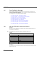
Value
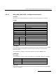
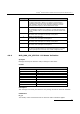
Clock Mode
0
No change
1
CT bus Primary Master, driving Clock Set A
2
CT bus Secondary Master, driving Clock Set B
3
CT bus Slave, initially using Clock Set A
4
CT bus disabled
10
CT bus Primary Master, driving Clock Set B
11
CT bus Secondary Master, driving Clock Set A
12
CT bus Slave, initially using Clock Set B
When mode 4 is selected ("CT bus disabled"), the DSI SPCI Board is electrically
isolated from the other boards using the CT bus. The CT bus connection commands
may still be used, but the connections made are only visible to this board. The on-
board clocks are synchronized to the configured pll_clk_src reference.
If the DSI SPCI Board is configured to be Slave to the CT bus, then it automatically
switches between using Clock Set A and Clock Set B if it detects a failure on the
current clock set.
When a board is acting as Primary Master, it uses the clock reference set by the
pll_clk_src parameter to drive the CT bus clock.
As Secondary Master, the pll_clk_src must be set to an appropriate source ready for
use if the board acting as Primary Master stops driving the CT bus clock. Until this
time, the on-board clocks on the Secondary Master board are synchronized to the CT
bus clock provided by the Primary Master.
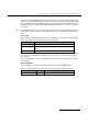
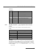
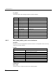
pll_clk_src
This parameter determines the source of the PLL reference clock, the permissible
values are:
Value
PLL Clock Source
0
No change
1
Clock recovered from one of the line interfaces according to priority
order.
5
Local reference oscillator
7
NETREF 1
The PLL clock is used as the reference when acting as CT bus Primary Master.
If the clock is to be recovered from one of the line interfaces then the highest-priority
in sync line interface is used as the reference. Each line interface is assigned a priority:
by default liu_id=0 is the highest priority and liu_id=7 the lowest. The user may
modify the priority order by sending the MVD_MSG_CLOCK_PRI message. If none of
the interfaces are available for recovery, then the phase locked loop runs in holdover
mode, outputting a clock with the same frequency as the last valid signal. When a valid
signal returns, it waits for a short period to verify that it is stable and then
automatically switches to use it as the clock reference.