
Specifications


Dialogic
®
DSI SPCI Network Interface Boards Programmer's Manual Issue 7
29
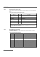
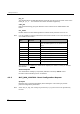
0
1
Primary Master, A Channel - The board drives CT bus clock set A
using the clock source selected by bit 0 of this flags parameter.
1
0
Secondary Master, B Channel - The board is configured to drive
clock set B in Secondary Master mode. The on-board clocks are
synchronized to the CT bus clock set A. It will automatically switch
to become Primary Master if the board driving clock set A fails.
1
1
Slave, initially A Channel – The board uses the CT bus clocks,
which must be generated by another board on the CT bus. Initially
the board recovers from clock set A, though will switch over
automatically to recover from clock set B if set A fails.
Bit 13 is set to 1 to cause the board to drive the CT_NETREF1 clocks on the CT bus.
The highest priority in-sync line interface is used as a clock source. If this bit is set to
zero then CT_NETREF1 clock is not driven.
All other bits are reserved and must be set to zero.
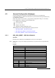
l2_flags - level 2 flags
Bit 1 is set to 1 for ANSI operation or zero for ITU-T operation.
Bit 3 is set to 1 for ANSI operation or zero for ITU-T operation.
Bit 5 is set to 1 to cause Link Status Signal Units (LSSU) to have a two octet status
field. Usually this bit is set to zero, and LSSUs have a single octet status field.
All other bits are reserved for future use and must be set to zero.
max_sif_len - maximum Signaling Information Field length
The maximum Signaling Information Field length in octets that is permitted over the
signaling link. Usually set to 272 although it may be set to 62 for inter-working with
switches that do not support 272 octet messages.
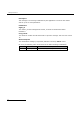
l3_flags - level 3 flags
Bit 0 is set to 1 to disable the level 3 discrimination function (allowing the signaling
point to receive all messages irrespective of the destination point code contained in the
message) or zero to allow the discrimination function to function normally.
Bit 1 is set to 1 to disable sub-service field (SSF) discrimination. If this bit is set to
zero, received MSUs whose ssf values do not match the configured ssf value are
discarded.
Bit 8 is set to 1 to select ANSI operation or zero for ITU-T operation.
Bit 9 is set to 1 to select ANSI style 24 bit point codes in the MTP routing label or zero
to select ITU-T style 14 bit point codes. This bit must be set to 1 if ANSI operation is
selected.
Bit 10 is set to 1 for ANSI operation or zero for ITU-T operation.
Bit 11 is set to 1 for ANSI operation or zero for ITU-T operation.
All other bits are reserved for future use and must be set to zero.
Note: For ANSI operation bits 8, 9, 10, and 11 must all be set to 1.
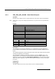
pc - point code
The pure binary representation of this signaling point code. Must be in the range 0 to
16383 for 14 bit point code operation, or 0 to 16777215 for 24 bit point code
operation.