
Specifications

3 SPCI Board Configuration and Operation
16
The ss7.dc3 code file which should be used for DSI SPCI boards running SS7
protocols.
The mon.dc3 code file which should be used for DSI SPCI boards running
monitoring applications.
Note: The *.dc3 code file are distributed as part of the Dialogic
®
DSI Development Package.
The code file requires a license button to be fitted to the board which enables the
software to run on the board, details are given in Section 2.3 License Buttons on page
12.
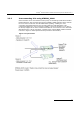
3.3 Using the CT bus
The DSI SPCI2S and DSI SPCI4 boards support two or four T1/E1 Line Interface Units
and a CT bus interface (H.100) respectively. The on-board signaling processor handles
the SS7 signaling timeslots whilst the remaining circuits (voice or data bearer circuits)
are passed to the CT bus for distribution to other boards.
All communication between the application and the board is message-based. Initial
configuration is usually handled by the configuration utility s7_mgt, which takes
commands from the text file (config.txt) and generates all the necessary
configuration messages for the board. Subsequent operation is entirely message
driven, messages being passed in both directions between the board and the
application.
One of the roles of the application is to control the dynamic switching between the CT
bus and the T1/E1 line interfaces. This section provides details of how to interface with
the CT bus, including the initial (static) configuration and the subsequent (dynamic)
switching.
The operation of the CT bus switching interface is described in terms of the SCbus
switching model using the messages MVD_SC_DRIVE_LIU, MVD_MSG_SC_LISTEN
and MVD_MSG_SC_FIXDATA and config.txt commands LIU_SC_DRIVE and
SCBUS_LISTEN.
3.3.1 Switching Model
The basic switching model assumes that at system initialization all incoming T1/E1
timeslots and all resource board output timeslots are connected up to channels on the
CT bus and that these connections are never changed. This has the advantage that
once the on-board CT bus drivers have been set up they are never changed so the
chances of inadvertently causing CT bus conflict is minimized. It also means that the
user can predict the exact CT bus channels where any input timeslot can be located
and this in turn can assist with fault diagnosis and general system test.
It is also possible to generate fixed patterns on any T1/E1 output timeslots to provide
the correct idle pattern for presentation to the network on all circuits where there is no
active call.
Having completed the system initialization, all drives to the CT bus are set up. Then,
on a dynamic (call by call) basis, the connectivity must be modified when a new call
arrives and when it finishes.
When a new call arrives, the application, in general, needs to initiate two listen
commands. One command causes the resource to listen to the appropriate CT bus
channel to hear the incoming voice path and the other causes the T1/E1 interface to
listen to the output from the resource board to generate the outgoing voice path.