Dialogic ® DSI SPCI Network Interface Boards Programmer's Manual April 2012 U03HSP www.dialogic.
Copyright and Legal Notice Copyright © 1993-2012 Dialogic Inc. All Rights Reserved. You may not reproduce this document in whole or in part without permission in writing from Dialogic Inc. at the address provided below. All contents of this document are furnished for informational use only and are subject to change without notice and do not represent a commitment on the part of Dialogic Inc. and its affiliates or subsidiaries (“Dialogic”).
Dialogic® DSI SPCI Network Interface Boards Programmer's Manual Issue 7 Contents 1 Introduction ........................................................................................................ 6 1.1 Related Information ................................................................................................................ 6 2 Specification........................................................................................................ 8 2.1 2.2 2.4 2.
Contents 4.5 4.4.1 SSD_MSG_STATE_IND - Board Status Indication.......................................................... 56 4.4.2 API_MSG_CNF_IND - s7_mgt Completion Status Indication ........................................... 57 4.4.3 MVD_MSG_CLK_IND - Clock Event Indication .............................................................. 58 4.4.4 MVD_MSG_LIU_STATUS - LIU Status Indication ........................................................... 59 4.4.5 MGT_MSG_EVENT_IND - Error Indication ...........
Dialogic® DSI SPCI Network Interface Boards Programmer's Manual Issue 7 Revision History Issue Date Description 7 04-Apr-12 Re-structured manual. Configuration and installation details moved to DSI Software Environment Programmer’s Manual. 6 12-Feb-10 Updated to reflect changed support for Windows®. SWITCH_XCON command documented. 5 20-Mar-09 Clarification to ISUP-S and TUP-S protocol dimensioning. 4 05-Mar-09 Removed CPM8 specific content as product is now EOL. Updated to Dialogic® branding.
1 Introduction 1 Introduction The range of Dialogic® DSI SPCI Network Interface Boards includes specialized T1/E1 SS7 signaling boards for use in PCI host computer systems. All boards offer a common interface to the application allowing applications to be easily ported between hardware architectures. This Programmer’s Manual relates to the low density Dialogic® DSI SPCI4 Network Interface Boards and Dialogic® DSI SPCI2S Network Interface Boards.
Dialogic® DSI SPCI Network Interface Boards Programmer's Manual Issue 7 Current software and documentation supporting Dialogic® DSI products is available at http://www.dialogic.com/support/helpweb/signaling Product data sheets are available at http://www.dialogic.com/support/helpweb/signaling For more information on Dialogic® DSI SS7 products and solutions, visit http://www.dialogic.
2 Specification 2 Specification This section provides information about: Product Identification Dialogic® DSI SPCI Network Interface Board License Buttons SNMP Support Regulatory and Geographic Considerations 2.
Dialogic® DSI SPCI Network Interface Boards Programmer's Manual Issue 7 2.2.2 Host Interface The DSI SPCI board is a 32-bit PCI board, but can also be installed in 64-bit PCI slots. The board is keyed as universal and can be installed in either 5 V or 3.3 V signaling environment slots. 2.2.3 Physical Interfaces The DSI SPCI board supports the following physical interfaces: • DSI SPCI4 - Four T1/E1 digital trunk interfaces. See Section 2.3.1, “Run Modes” below for more detail.
2 Specification Data Rate — 48kbit/s, 56 kbit/s, 64 kbit/s or external. 2.2.3.3 H.100 CT Bus An H.100 CT Bus interface is provided to allow connection to other H.100 compatible boards. The H.100 CT Bus supports 4096 channels (or timeslots) and the associated clock and framing signals. This board is capable of generating the CT Bus clocks, or can act as a slave. CT Bus channels may be used individually, or grouped to provide a higher bandwidth data path.
Dialogic® DSI SPCI Network Interface Boards Programmer's Manual Issue 7 2.2.7 Physical Specification Form factor standard height, full length PCI board Dimensions Board Length 341 mm (13.425 inches) Height 106 mm (4.17 inches) Packaged Length 406.4 mm (16 inches) Width 219 mm (8.625 inches) Height 44.5 mm (1.75 inches) Weight Board DSI SPCI2S 211 g DSI SPCI4 180 g Packaged board 2.2.
2 Specification Supplied with each product and provides a list of the specifications to which the DSI SPCI board conforms. • International Declaration of Conformity See http://www.dialogic.com/declarations • Country-Specific Approvals See the Global Product Approvals list at http://www.dialogic.com/declarations Alternatively, contact your Dialogic technical sales representative for more information. 2.2.
Dialogic® DSI SPCI Network Interface Boards Programmer's Manual Issue 7 2.3.
2 Specification The Dialogic® DSMI MIBs are distributed within the Dialogic® DSI SS7 Development Package in the /opt/DSI sub-directory as a compressed ZIP file: dsi-mibs.zip. For details of the DSMI SNMP MIBs supported, events, SNMP traps and configuration refer to the Dialogic® DSI Protocol Stacks SNMP User Manual. 2.
Dialogic® DSI SPCI Network Interface Boards Programmer's Manual Issue 7 3 SPCI Board Configuration and Operation Before attempting software configuration, you should gain an understanding of the flexibility of the protocol stack, the run-time options that exist and the mechanisms that are used to select specific features. This section gives an overview of these options.
3 SPCI Board Configuration and Operation The ss7.dc3 code file which should be used for DSI SPCI boards running SS7 protocols. The mon.dc3 code file which should be used for DSI SPCI boards running monitoring applications. Note: The *.dc3 code file are distributed as part of the Dialogic® DSI Development Package. The code file requires a license button to be fitted to the board which enables the software to run on the board, details are given in Section 2.3 License Buttons on page 12. 3.
Dialogic® DSI SPCI Network Interface Boards Programmer's Manual Issue 7 When a call clears, the application needs to initiate generation of the fixed idle pattern towards the network operation (and may wish to connect an idle pattern to the resource board). 3.3.2 Static Initialization Static initialization is handled by the s7_mgt utility. For each T1/E1 line interface unit, user must include an LIU_SC_DRIVE command in the config.txt file.
3 SPCI Board Configuration and Operation #define OUR_MOD_ID #include #include #include #include #include #include (0xef) "system.h" "msg.h" "libc.h" "sysgct.h" "pack.h" "ss7_inc.
Dialogic® DSI SPCI Network Interface Boards Programmer's Manual Issue 7 3.3.5 Interconnecting LIUs using STREAM_XCON Interconnection of two Line Interface Units (LIUs) on the Dialogic® DSI SPCI Interface Network Board is also supported through the STREAM_XCON command which controls the cross connect switch on the DSI SPCI Board signaling, enabling the cross connection of timeslots between any two LIUs within the DSI SPCI Board.
4 Message Reference 4 4.1 Message Reference Overview This section describes the individual messages that may be sent to and received from the Dialogic® DSI SPCI Network Interface Board. Some messages are sent by the user's application software whilst others are sent by utility programs such as the s7_mgt protocol configuration utility. Prior to sending any message to the board, the application should call the GCT_set_instance( ) library function to select which board the message will be sent to.
Dialogic® DSI SPCI Network Interface Boards Programmer's Manual Issue 7 Message Type Mnemonic Description 0x3e15 Confirmation of MVD_MSG_SC_FIXDATA 0x3e17 Confirmation of MVD_MSG_SC_LISTEN 0x3e18 Confirmation of MVD_MSG_SC_DRIVE_LIU 0x3e19 Confirmation of MVD_MSG_SC_MULTI_CONNECT 0x3e1f Confirmation of MVD_MSG_SC_CONNECT 0x3e20 Confirmation of MVD_MSG_CNFCLOCK 0x3e21 Confirmation of MVD_MSG_CLK_PRI 0x3e34 Confirmation of LIU_MSG_CONFIG 0x3e35 Confirmation of LIU_MSG_CONTROL 0x3f10 Con
4 Message Reference 4.1.2 Board-specific Module IDs Table 5 lists the software modules IDs (by mnemonic and value) used on the DSI SPCI Board. Table 5.
Dialogic® DSI SPCI Network Interface Boards Programmer's Manual Issue 7 4.2 General Configuration Messages General configuration messages are typically issued by the s7_mgt protocol configuration utility, in which case they need not, and should not, be generated by any user application software.
4 Message Reference Description This message is used during initialization by the application to reset the ssd module and set up its run-time parameters. Parameters mgmt_id The module_id of the management module, to which ssd sends board status indications. num_boards The maximum number of boards that ssd is required to manage. This must not exceed 16. Status Response The confirmation message (if requested) indicates success by status of zero.
Dialogic® DSI SPCI Network Interface Boards Programmer's Manual Issue 7 4.2.2 SSD_MSG_RST_BOARD - Board Reset Request Synopsis Message sent to SSD to cause a single board to be reset and a code file downloaded. Note: When using s7_mgt, this message is generated by s7_mgt and must not be generated by the user.
4 Message Reference phy_id The physical ID for the DSI SPCI Board. This field must be set to the same value as the board_id. (i.e., 0 … one less than the number of boards supported). code_file Null terminated string giving the filename of the code file to be downloaded to the board. run_mode Number taken from the following table to indicate which protocols are to be run. Note: It is only possible to activate protocols that have been licensed to run on the board by use of a suitable license button.
Dialogic® DSI SPCI Network Interface Boards Programmer's Manual Issue 7 Format MESSAGE HEADER Field Name Meaning type MGT_MSG_CONFIG0 (0x7F10) id 0 src Sending module's module_id dst MGMT_TASK_ID (0x8e) rsp_req used to request a confirmation hclass 0 status Status Response (if confirmation requested) err_info 0 len 68 PARAMETER AREA Offset Size Name 0 2 config_type (Must be set to 2) 2 2 flags 4 2 l1_flags 6 2 l2_flags 8 2 max_sif_len 10 2 l3_flags 12 4 pc 16 2
4 Message Reference Description This message must be the first message sent to the DSI SPCI Board once the SS7 software is running. It is used to configure all modules on the board for operation. The message contains signaling point codes for this signaling point and the adjacent signaling point(s), flags to permit various level 1, level 2, and level 3 run-time options to be selected and the physical link parameters.
Dialogic® DSI SPCI Network Interface Boards Programmer's Manual Issue 7 0 1 Primary Master, A Channel - The board drives CT bus clock set A using the clock source selected by bit 0 of this flags parameter. 1 0 Secondary Master, B Channel - The board is configured to drive clock set B in Secondary Master mode. The on-board clocks are synchronized to the CT bus clock set A. It will automatically switch to become Primary Master if the board driving clock set A fails.
4 Message Reference ssf - sub-service field The value used in the sub-service field of all messages generated by level 3. Must be in the range 0 to 15. For ANSI operation, the 2 least significant bits must be set to 1. up_enable - User Part Enable A 16 bit mask used to enable or disable reception of messages on a per user part basis. If bit N is set to 1, then messages for user part N are received by the signaling point.
Dialogic® DSI SPCI Network Interface Boards Programmer's Manual Issue 7 Link Serial Port 0 B 1 A 2 Cannot be used for a serial port. 3 Cannot be used for a serial port. Bit 15 is set to 1 to disable the link, or zero to enable the link. All other bits are reserved for future use and must be set to zero. linkn_slc - Signaling link code The signaling link code for the link, which must be in the range 0 to 15.
4 Message Reference 4.3 Hardware Control Messages Hardware control messages are used to control various hardware devices on the board including the T1/E1 Line Interface Units (LIUs), the digital cross connect switches and the clocking mode for the board. In a static configuration, all these hardware blocks can be set up using the s7_mgt protocol configuration utility along with the appropriate commands in the config.txt protocol configuration file.
Dialogic® DSI SPCI Network Interface Boards Programmer's Manual Issue 7 Format MESSAGE HEADER Field Name Meaning type LIU_MSG_CONFIG (0x7e34) id liu_id src Sending Module ID dst MVD_TASK_ID (0x10) rsp_req used to request a confirmation hclass 0 status Status Response (if confirmation requested)0 err_info 0 len 40 PARAMETER AREA Offset Size Name 0 1 liu_type 1 1 line_code 2 1 frame_format 3 1 crc_mode 4 1 build_out 5 1 faw 6 1 nfaw 7 4 Reserved for future use, mu
4 Message Reference Note: liu_type Description 1 Disabled (used to deactivate a LIU). In this mode the LIU does not produce an output signal. 3 E1 120ohm balanced interface. 4 T1 5 E1 120ohm balanced interface. This must be selected by the user to be appropriate for the actual hardware fitted otherwise an error status is returned. line_code The line coding technique taken from the following table: line_code Description 1 HDB3 (E1 only). 2 AMI with no Zero Code Suppression.
Dialogic® DSI SPCI Network Interface Boards Programmer's Manual Issue 7 faw The 8 bit value to be used for any E1 frame alignment word bit positions that are not modified by other options. This allows the spare bit designated "For International Use" to be set by the user when CRC4 mode is disabled. Valid values are 0x9b or 0x1b. When using T1, this parameter must be set to zero. [E1 default = 0x9b].
4 Message Reference 4.3.2 LIU_MSG_CONTROL - LIU Control Request Synopsis Message sent by the application to dynamically control operation for a Line Interface Unit (LIU). Allows setting of outgoing alarms and diagnostic loopbacks.
Dialogic® DSI SPCI Network Interface Boards Programmer's Manual Issue 7 rai_gen Description 0 Do not change RAI / Yellow alarm generation mode. 1 Disabled - do not generate RAI / Yellow alarm. 2 Forced active - generate RAI / Yellow alarm. 3 Automatic generation of RAI / Yellow alarm upon loss of synchronization. loop_mode The diagnostic loop back mode taken from the following table: loop_mode Description 0 Do not change diagnostic loop back mode. 1 Disabled - remove any diagnostic loop.
4 Message Reference 4.3.3 LIU_MSG_R_CONFIG - LIU Read Configuration Request Synopsis Message sent by the application to read back the current LIU configuration from the DSI SPCI Board.
Dialogic® DSI SPCI Network Interface Boards Programmer's Manual Issue 7 Value 4.3.4 Mnemonic Description 0x01 None Invalid framer ID. 0x02 None Invalid message length. 0x03 None Control parameters are not consistent with the type of device being controlled or with each other. LIU_MSG_R_CONTROL - LIU Read Control Request Synopsis Message sent by the application to read back the current Line Interface Unit (LIU) control options from the board.
4 Message Reference Value 4.3.5 Mnemonic Description 0x01 None Invalid framer ID. 0xff None Invalid message length. MVD_MSG_SC_DRIVE_LIU - LIU CT bus Initialization Request Synopsis This message is sent to the board at initialization time to set up a static switch path through the board between the Line Interface Unit (LIU) and the CT bus.
Dialogic® DSI SPCI Network Interface Boards Programmer's Manual Issue 7 ts_mask A 32 bit timeslot mask where each bit position is set to 1 if the corresponding timeslot on the T1/E1 interface is required to be connected to the CT bus. The least significant bit (bit 0) represents timeslot 0. Each timeslot for which the corresponding bit is set in ts_mask is connected up to the CT bus, other timeslots are not affected in any way.
4 Message Reference 4.3.6 MVD_MSG_SC_LISTEN - CT bus Listen Request Synopsis Message sent to the DSI SPCI Board to establish a connection from the CT bus to an outgoing timeslot on an T1/E1 Line Interface Unit (LIU).
Dialogic® DSI SPCI Network Interface Boards Programmer's Manual Issue 7 Parameters liu_id The identifier of the T1/E1 Line Interface Unit in the range 0 to one less than the number of LIUs fitted. This parameter can also be set to the special value 0x83 to select the signaling processor instead of an LIU. In this case, timeslots 0 ... 3 correspond to signaling processor 0 ... 3 respectively. Note: For the DSI SPCI2S, valid values for the LIU identifiers are 2 and 3.
4 Message Reference 4.3.7 MVD_MSG_SC_FIXDATA - Fixed Data Output Request Synopsis Message sent to the DSI SPCI Board in order to generate a fixed pattern on a specific T1/E1 Line Interface Unit timeslot.
Dialogic® DSI SPCI Network Interface Boards Programmer's Manual Issue 7 Status Response The confirmation message (if requested) indicates success by status of zero. On error, the following status values can be found in the confirmation message. Value 4.3.8 Mnemonic Description 0xd2 MVIP_INVALID_STREAM Invalid stream specified in listen request. 0xd3 MVIP_INVALID_TIMESLOT Invalid timeslot specified in listen request. 0xff None Fixed pattern generation request failed.
4 Message Reference Note: This message provides an alternative approach for controlling switching through the CT bus switch allowing connections to the CT bus to be utilized only as required (rather than being set up at initialization time).
Dialogic® DSI SPCI Network Interface Boards Programmer's Manual Issue 7 6 * * 10 * * 11 * * * * 12 * * * * * If a parameter is not required, it must be set to zero. local_stream The local stream defines which local stream to use for all the modes of operation. The local streams are either an liu_id or a special identifier to allow connection to the signaling processor as follows: Local Stream Connected to 0 ... 3 liu_id 0 ...
4 Message Reference mode = 6 : Remove a duplex connection between 2 timeslots on the CT bus and 1 timeslot on the local bus. Using parameters local_stream and local_slot, to specify both timeslots for disconnection. mode = 10 : Generate a fixed pattern (e.g., idle pattern) on a local timeslot. local_stream specifies the liu_id, local_slot the timeslot, and pattern the 8 bit data to be output on the timeslot. mode = 11 : Make a simplex connection between two local bus timeslots (without using the CT bus).
Dialogic® DSI SPCI Network Interface Boards Programmer's Manual Issue 7 Value 4.3.10 Mnemonic Description 0xd2 MVIP_INVALID_STREAM Invalid stream specified in listen request. 0xd3 MVIP_INVALID_TIMESLOT Invalid timeslot specified in listen request. 0xff None Invalid message length. MVD_MSG_SC_MULTI_CONNECT - Multiple Connect Request Synopsis Message sent to the board to control the switch to connect multiple paths.
4 Message Reference timeslot_mask A 32-bit mask representing up to 32 timeslots on the local stream. Bit 0 corresponds to timeslot 0. A 1 in the mask indicates that the pattern should be output on this timeslot, a 0 indicates that it should be left unchanged. mode The mode of operation. The following table shows the permitted values and their meaning. Value Description 1 Make a simplex connection between an cross connect switch timeslot and a local LIU stream.
Dialogic® DSI SPCI Network Interface Boards Programmer's Manual Issue 7 4.3.11 MVD_MSG_CNFCLOCK - Configure Clock Request Synopsis Message sent to a DSI SPCI Board to configure the clocking mode for the board.
4 Message Reference Value Clock Mode 0 No change 1 CT bus Primary Master, driving Clock Set A 2 CT bus Secondary Master, driving Clock Set B 3 CT bus Slave, initially using Clock Set A 4 CT bus disabled 10 CT bus Primary Master, driving Clock Set B 11 CT bus Secondary Master, driving Clock Set A 12 CT bus Slave, initially using Clock Set B When mode 4 is selected ("CT bus disabled"), the DSI SPCI Board is electrically isolated from the other boards using the CT bus.
Dialogic® DSI SPCI Network Interface Boards Programmer's Manual Issue 7 If using one of the NETREF signals as the reference source, then another board in the system must be providing this reference by driving a clock source onto the appropriate CT bus NETREF lines. If the NETREF signal is lost, the board continues with the PLL in holdover mode until another MVD_MSG_CNFCLOCK message is received to switch to a new mode.
4 Message Reference 4.3.12 MVD_MSG_CLOCK_PRI - Configure Clock Priority Request Synopsis Message sent to a DSI SPCI Board to configure the clock recovery priority order.
Dialogic® DSI SPCI Network Interface Boards Programmer's Manual Issue 7 Value 0 1 … 32 255 Meaning No change to the interface’s priority. New priority value for the line interface. The value 1 indicates highest priority, 32 the lowest priority. If two interfaces are given the same priority, the lowest-numbered interface is used first. Special value indicating that the line interface must not be used for clock recovery.
4 Message Reference 4.4 Event Indication Messages Event indication messages are the mechanism by which protocol and software error events are reported to the application. These messages are generated asynchronously by different modules within the stack. The messages in the event indication category include: 4.4.
Dialogic® DSI SPCI Network Interface Boards Programmer's Manual Issue 7 Parameters Board Status Value 4.4.2 Mnemonic Description 0x60 SSDSI_RESET Processor successfully reset. 0x62 SSDSI_FAILURE Failure to reset board. 0x64 SSDSI_BRD_RMVD Board removed (hot swap only). 0x65 SSDSI_BRD_INS Board inserted (hot swap only). 0x66 SSDSI_LIC_FAIL License validation failure. 0x67 SSDSI_LIC_CRP License corruption. 0x70 SSDSI_BCONG_CLR Message congestion towards board cleared.
4 Message Reference Note: It is recommended that the user invoke this option and then wait for the API_MSG_CNF_IND message to ensure the application does not attempt to send messages until initial configuration is complete. Parameters Completion Status The result of initial configuration coded as follows: Value 4.4.3 Meaning 0 Success 1 Error opening config.txt file 2 Syntax or value error in config.
Dialogic® DSI SPCI Network Interface Boards Programmer's Manual Issue 7 event_id 4.4.4 Description 1 PLL entered hold-over mode Issued by boards acting as primary or secondary clock master when its nominated clock reference becomes unavailable. The phase-locked-loop starts operating in “hold-over” mode, continuing to generate an on-board clock at the same frequency as the last valid reference signal.
4 Message Reference liu_status The status field in the message header is coded as follows: Value 4.4.
Dialogic® DSI SPCI Network Interface Boards Programmer's Manual Issue 7 Value Mnemonic ID Description 0x31 S7E_RESET_ERR MTP2 Failed to initialize. 0x33 S7E_POOL_EMPTY l2_llid No free buffers in MTP2 transmit pool. 0x34 S7E_TX_FAIL l2_llid Failed to send LSSU/FISU to driver. 0x35 S7E_HDR_ERR l2_llid No room to add level 2 header, SU not transmitted. 0x36 S7E_LEN_ERR l2_llid Length Error, SU not transmitted.
4 Message Reference 4.4.6 MGT_MSG_SS7_STATE - MTP2 Level 2 State Indication Synopsis Indication issued by the board every time the level 2 link state control state machine changes state. Format MESSAGE HEADER Field Name Meaning type MGT_MSG_SS7_STATE (0x0201) id llid (Level 2 logical link id - 0 ...
Dialogic® DSI SPCI Network Interface Boards Programmer's Manual Issue 7 Format MESSAGE HEADER Field Name Meaning type MGT_MSG_SS7_EVENT (0x0202) id l2_llid src MTP2 module id dst Management module id rsp_req 0 hclass 0 status Event Code (see below) err_info Timestamp next 0 len 0 Description This primitive is used by MTP2 to advise management of the occurrence of protocol related events in accordance with Q.752.
4 Message Reference Value 4.4.8 Mnemonic Description 33 S7T_T2_EXP Timer T2 expiry 34 S7T_T3_EXP Timer T3 expiry 48 S7P_AERM Failed proving attempt MGT_MSG_MTP_EVENT - MTP3 Q.752 Event Indication Synopsis Message issued by MTP3 to notify management of various protocol events in accordance with ITU-T Q.752.
Dialogic® DSI SPCI Network Interface Boards Programmer's Manual Issue 7 Value Mnemonic Paramter Description 1 MTPEV_CO link Changeover 2 MTPEV_CB link Changeback 3 MTPEV_REST link Restoration commenced 4 MTPEV_RPO link Remote processor outage 5 MTPEV_RPO_CLR link Remote processor outage cleared 6 MTPEV_CONG link Signaling link congestion 7 MTPEV_CONG_CLR link Congestion cleared 8 MTPEV_CONG_DIS link MSU discarded due to congestion 9 MTPEV_LS_LOST linkset Link set fail
4 Message Reference 4.5 Status Request Messages Status request messages can be used to poll the status of modules or systems running on the board. The messages in the status request category include: 4.5.1 LIU_MSG_R_STATE - LIU State Request LIU_MSG_R_STATS - LIU Read Statistics Request MGT_MSG_R_BRDINFO - Read Board Info Request LIU_MSG_R_STATE - LIU State Request Synopsis Message sent by the application to read the current state of a Line Interface Unit (LIU).
Dialogic® DSI SPCI Network Interface Boards Programmer's Manual Issue 7 State Description 0 OK 1 PCM Loss 2 AIS 3 Sync Loss 4 Remote Alarm Status Response The confirmation message (if requested) indicates success by status of zero. On error, the following status values can be found in the confirmation message. Value Mnemonic Description 0x01 None Invalid framer ID. 0xff None Invalid message length.
4 Message Reference 4.5.2 LIU_MSG_R_STATS - LIU Read Statistics Request Synopsis Message used to read back performance statistics associated with a Line Interface Unit (LIU). Format MESSAGE HEADER Field Name Meaning type id src dst rsp_req hclass status LIU_MSG_R_STATS (0x5e36) liu_id (in the range 0 to one less than the number of LIUs) Sending module ID MVD_module_ID Used to request a confirmation.
Dialogic® DSI SPCI Network Interface Boards Programmer's Manual Issue 7 Typically, a managing application would be set up to periodically (for example, hourly or daily) read and reset the statistics and store the resulting information so that it can be accessed later for generation of performance reports for the line interface. Parameters The LIU_MSG_R_STATE message includes the following parameters: version Version of the parameter area.
4 Message Reference prbs_status The status of Pseudo Random Bit Sequence (PRBS) indications. - 1 = PRBS is valid, the counts are correct. - 3 = PRBS sequence is not synchronized. 4.5.3 MGT_MSG_R_BRDINFO - Read Board Info Request Synopsis Message used to request basic board information.
Dialogic® DSI SPCI Network Interface Boards Programmer's Manual Issue 7 Value 2 Mnemonic Meaning BRDINFO_BTYPE_SPCI SPCI2S or SPCI4 board board_rev The DSI SPCI Board hardware revision number. swa The setting of the board's rotary switch labeled "Boot". Note: The switch should be set to 8. swb Geographic addressing switch setting, that is, the address at which the board appears when the -o3 feature of ssds is used. prom_maj_rev Firmware major revision number.
Protocol Configuration Using Discrete Messages Protocol Configuration Using Discrete Messages This appendix provides guidelines for protocol configuration using individual messages. A.
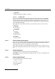
Dialogic® DSI SPCI Network Interface Boards Programmer's Manual Issue 7 8. Build and send an MTP3 Module Configuration Request (MTP_MSG_CONFIG) to set up configuration parameters that relate to the MTP3 environment (number of link sets and links to support, module_ids for user part modules etc.). See the MTP3 Programmer’s Manual for the message definition. Wait for the confirmation message and check the status. For each link set in the system perform the following: 9.
Protocol Configuration Using Discrete Messages Figure 2 Protocol Configuration Message Sequence Diagram MTP2 USER_MGT SSD SSD_MSG_RESET (0x7680) On-Board MGT MTP3 MTP2 CTSWX Repeated per board (0x3680) Geographic Addressing only SSD_MSG_BOARD_INFO (0x7689) (0x3689) SSD_MSG_RST_BOARD (0x7681) Repeated per LIU (0x3681) SSD_MSG_STATE_IND (0x06a0) MGT_MSG_CONFIG0 (0x7f10) (0x3f10) Repeated per Link LIU_MSG_CONFIG (0x7e34) (0x3e34) MGT_MSG_L1_CONFIG (0x7f17) (0x3f17) SS7_MSG_CONFIG (0x7203) P