
User's Manual
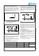
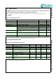
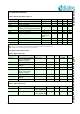
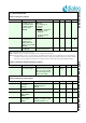
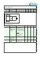
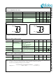
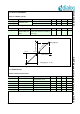
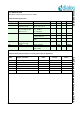
Table Of Contents
- 1.0 Connection diagram
- 2.0 Introduction
- 3.0 Specifications
- 3.1 GENERAL
- 3.2 ABSOLUTE MAXIMUM RATINGS
- 3.3 Operating Conditions
- 3.4 Digital Input/Output Pins
- 3.5 ULTRA LOW ENERGY (ULE) I/O PIN
- 3.6 SUPPLY CURRENTS
- 3.7 Analog Front End
- Table 10: Microphone amplifier
- Table 11: Microphone amplifier (Operating Condition)
- Table 12: Microphone supply voltages
- Table 13: VREFp load circuit
- Table 14: LSRp/LSRn outputs
- Table 15: LSRp/LSRn load circuits
- Table 16: PAOUTp, PAOUTn outputs
- Table 17: PAOUTp, PAOUTn outputs (Note 21)
- Table 18: PAOUTp, PAOUTn external components
- 3.8 Battery management
- 3.9 Baseband Part
- 3.10 Radio (RF) Part
- 3.11 RF Power supply
- 3.12 RF channel frequencies
- 4.0 Design guidelines
- 5.0 Notices to OEM
- 6.0 Package information
- 7.0 Revision history

SC14SPNODE SF DECT Module with integrated Antenna and FLASH
© 2012 Dialog Semiconductor B.V. 14 Jul 1, 2014 v1.6
3.5 ULTRA LOW ENERGY (ULE) I/O PIN
3.6 SUPPLY CURRENTS
Note 15: PAOUTp and PAOUTn have internal fixed resistors connected to VSSPA. The values are 5 k if CLASSD[CLASSD_VOUT] = 01, else
6k. So in digital mode with a ‘1’ on output a small static current will flow.
Table 8: ULP_PORT specifications
PARAMETER DESCRIPTION CONDITIONS MIN TYP MAX UNITS
Vil_ulp Logic 0 input level; pin
ULP_PORT
Vbat = 2.1 V to
3.45 V
0.2*Vbat V
Vih_ulp Logic 1 input level; pin
ULP_PORT
Vbat = 2.1 V to
3.45 V
0.8*Vbat V
Vol_ulp Logic 0 output level; pin
ULP_PORT
Iout = 1 mA,
Vbat = 2.4 V
0.2*Vbat V
Voh_ulp Logic 1 output level; pin
ULP_PORT
Iout = 1 mA,
Vbat = 2.4 V
0.8*Vbat V
Ipull_up_ulp Input current with pull up
enabled; pin ULP_PORT
Vin = GND 2.5 A
Ipull_down_ulp Input current with pull down
enabled; pin ULP_PORT
Vin = Vbat; Vbat =
2.1 V to 3.45 V
2.5 A
Table 9: Supply currents (indicative value)
PARAMETER DESCRIPTION CONDITIONS MIN TYP MAX Unit
Iavd_pa CLASSD normal
mode supply current
at AVD
CLASSD_PD=0 3.5 mA
Iavd_paport CLASSD digital port
mode supply current
at AVD
(P3_0_MODE = 00 or P3_1_MODE
= 00) and CLASSD_PD=1.
(Note 15)
5 A