
User's Manual
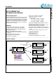
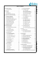
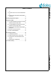
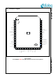
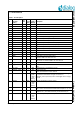
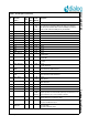
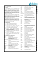
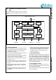
Table Of Contents
- 1.0 Connection diagram
- 2.0 Introduction
- 3.0 Cordless Voice Module functionality
- 4.0 Functional description
- 5.0 CAT-iq
- 6.0 Specifications
- 6.1 General
- 6.2 Absolute Maximum ratings
- 6.3 Operating Conditions
- 6.4 Digital Input/Output Pins
- 6.5 Analog Front End
- Table 11: Microphone amplifier
- Table 12: Microphone amplifier (Operating Condition)
- Table 13: Microphone supply voltages
- Table 14: VREFp load circuit
- Table 15: LSRp/LSRn outputs
- Table 16: LSRp/LSRn load circuits
- Table 17: PAOUTp, PAOUTn outputs
- Table 18: PAOUTp, PAOUTn outputs (Note 19)
- Table 19: PAOUTp, PAOUTn external components
- 6.6 Battery management
- 6.7 Baseband Part
- 6.8 Radio (RF) Part
- 6.9 RF Power supply
- 6.10 RF channel frequencies
- 7.0 Design guidelines
- 8.0 Example Application Diagram
- 9.0 Notices to OEM
- 10.0 Package information
- 11.0 Revision history

SC14CVMDECT SF Cordless Voice Module
© 2012 Dialog Semiconductor B.V. 5 July 1, 2014 v1.6
1.1 PIN DESCRIPTION
Table 1: Pin description
Pin
Module
Pin name
(Note 1)
In/
Out
Iout
Drive
(mA)
Reset
State
(Note 2)
Description
1GND - - -Ground
2 P0 O 8 Hi-Z Control port for FAD. See 4.13
3 RFP0 O 8 Hi-Z Control port for FAD. See 4.13
4 P0n O 8 Hi-Z Control port for FAD. See 4.13
5 RFP0n O 8 Hi-Z Control port for FAD. See 4.13
6GND - - -Ground
7 VREFp O - I Positive microphone supply voltage
8 MICp I - I Positive microphone input
9 MICn I - I Negative handset microphone input
10 MICh I - I Headset microphone input with fixed input protection
11 VREFm - - - Negative microphone reference (star point), connect to GND.
12 LSRp O - O Positive loudspeaker output
13 LSRn O - O Negative loudspeaker output
14 GND - - - Ground
15 P3[3] IO 8 I I/O Port
16 P1[0] IO 2 I-PU I/O Port
17 SOCp I - I Battery state of charge positive input.
Connect to GND if not used. See 4.9
18 SOCn I - I Battery state of charge negative input. Star point connected to the
SOC resistor. Connect to GND if not used. See 4.9
19 DC_SENSE I I Voltage sense input. Connect to GND if not used.
20 DC_I I I Current sense input of DC/DC converter. Connect to GND if not
used
21 DC_CTRL O 2 O-0 Switching clock for the DC/DC converter.
22 CHARGE_CTRL O 1 O-0 Charge control pin.
Leave unconnected if not used. See 4.9
23 CHARGE I - I-PD
(270k
fixed
pull-
down)
Charger connected indication. Switches on the device if voltage >
1.5 V. Must be connected to charger via resistor R >
(Vcharger_max-3 V)/10 mA (round to next largest value in range).
See 4.9
24 PAOUTp IO 500 O-0 (5k
fixed
pull-
down)
CLASSD loudspeaker positive outputs
25 VDDPA I - - CLASSD Audio Amplifier supply voltage up to 3.45 V.
GND or leave unconnected if CLASSD Audio Amplifier is not used.
26 CP_VOUT1 O - I Charge Pump Output 1.
A capacitor of 1 F to GND is internally connected to this pin.
27 PAOUTn IO 500 O-0 (5k
fixed
pull-
down)
CLASSD loudspeaker positive output