
User's Manual
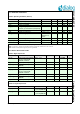
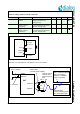
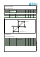
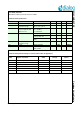
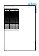
Table Of Contents
- 1.0 Connection diagram
- 2.0 Introduction
- 3.0 Cordless Voice Module functionality
- 4.0 Functional description
- 5.0 CAT-iq
- 6.0 Specifications
- 6.1 General
- 6.2 Absolute Maximum ratings
- 6.3 Operating Conditions
- 6.4 Digital Input/Output Pins
- 6.5 Analog Front End
- Table 11: Microphone amplifier
- Table 12: Microphone amplifier (Operating Condition)
- Table 13: Microphone supply voltages
- Table 14: VREFp load circuit
- Table 15: LSRp/LSRn outputs
- Table 16: LSRp/LSRn load circuits
- Table 17: PAOUTp, PAOUTn outputs
- Table 18: PAOUTp, PAOUTn outputs (Note 19)
- Table 19: PAOUTp, PAOUTn external components
- 6.6 Battery management
- 6.7 Baseband Part
- 6.8 Radio (RF) Part
- 6.9 RF Power supply
- 6.10 RF channel frequencies
- 7.0 Design guidelines
- 8.0 Example Application Diagram
- 9.0 Notices to OEM
- 10.0 Package information
- 11.0 Revision history

SC14CVMDECT SF Cordless Voice Module
© 2012 Dialog Semiconductor B.V. 39 July 1, 2014 v1.6
6.10 RF CHANNEL FREQUENCIES
RF setting values must be followed according to
AN-D-204 when DECT country mode was changed.
Table 26: RF frequencies and channel numbers
Frequency
(MHz)
DECT
CH
J-DECT
CH
DECT6.0
CH
1881.792 9
1883.520 8
1885.248 7
1886.976 6
1888.704 5
1890.432 4
1892.160 3
1893.888 2
1895.616 1 1
1897.344 0 0
1899.072 10
1900.800 11
1902.528 12
1921.536 4
1923.264 3
1924.992 2
1926.720 1
1928.448 0