
User's Manual
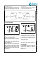
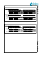
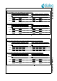
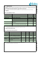
Table Of Contents
- 1.0 Connection diagram
- 2.0 Introduction
- 3.0 Cordless Voice Module functionality
- 4.0 Functional description
- 5.0 CAT-iq
- 6.0 Specifications
- 6.1 General
- 6.2 Absolute Maximum ratings
- 6.3 Operating Conditions
- 6.4 Digital Input/Output Pins
- 6.5 Analog Front End
- Table 11: Microphone amplifier
- Table 12: Microphone amplifier (Operating Condition)
- Table 13: Microphone supply voltages
- Table 14: VREFp load circuit
- Table 15: LSRp/LSRn outputs
- Table 16: LSRp/LSRn load circuits
- Table 17: PAOUTp, PAOUTn outputs
- Table 18: PAOUTp, PAOUTn outputs (Note 19)
- Table 19: PAOUTp, PAOUTn external components
- 6.6 Battery management
- 6.7 Baseband Part
- 6.8 Radio (RF) Part
- 6.9 RF Power supply
- 6.10 RF channel frequencies
- 7.0 Design guidelines
- 8.0 Example Application Diagram
- 9.0 Notices to OEM
- 10.0 Package information
- 11.0 Revision history

SC14CVMDECT SF Cordless Voice Module
© 2012 Dialog Semiconductor B.V. 30 July 1, 2014 v1.6
6.0 Specifications
All MIN/MAX specification limits are guaranteed by design, or production test, or statistical methods unless
note 7 is added to the parameter description. Typical values are informative.
Note 7: This parameter will not be tested in production. The MIN/MAX values are guaranteed by design and verified by characterization.
6.1 GENERAL
Note 8: The resulting range is very dependent of the mechanical design. Dialog Semiconductor is not responsible for this design and as such Dialog
Semiconductor is not responsible for the resulting performance range of the final product.
6.2 ABSOLUTE MAXIMUM RATINGS
Note 9: Absolute maximum ratings are those values that may be applied for maximum 50 hours.
Beyond these values, damage to the device may occur.
Table 6: SC14CVMDECT SF module
ITEM CONDITIONS VALUE UNIT
Dimensions l x w x h 18.0 x 19.6 x 2.7 mm
Weight 1.5 g
Temperature range -40 to +85 °C
Frequency range According to DECT standard 1870 to 1930 MHz
Antenna range According to DECT standard; (Note 8)
- typical outdoor 350 m
- typical indoor 75 m
Standards compliancy ETS 300 444 (DECT GAP), former TBR2214
FCC part 15
Power supply 2 cell NiCd/NiMH
Note: for 1 Li-Ion battery an external LDO is required.
2.10 to 3.45 V
Maximum PCB warpage For entire reflow range 0.1 mm
Table 7: Absolute Maximum Ratings (Note 9)
PARAMETER DESCRIPTION CONDITIONS MIN MAX UNIT
Vbat_max Max voltage on pin VBATIN, VDDPA 3.45 V
Vpon_max Max voltage on pin PON 5.5 V
Vled_max Max voltage on pin LED4, LED3 3.6 V
Vdig_bp_max Max voltage on digital pins with back drive
protection; ports P0 and P2 (except P2.6)
3.6 V
Vdig_max Max voltage on other digital pins 2.0 V
Vana_max Max voltage on analog pins 2.2 V
Vesd_hbm ESD voltage according to human body
model; all pins
2000 V
Vesd_mm ESD voltage according to machine model;
all pins
150 V