
User's Manual
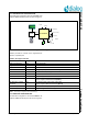
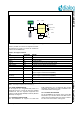
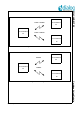
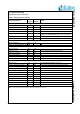
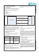
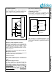
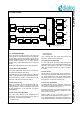
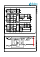
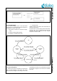
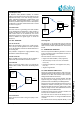
Table Of Contents
- 1.0 Connection diagram
- 2.0 Introduction
- 3.0 Cordless Voice Module functionality
- 4.0 Functional description
- 5.0 CAT-iq
- 6.0 Specifications
- 6.1 General
- 6.2 Absolute Maximum ratings
- 6.3 Operating Conditions
- 6.4 Digital Input/Output Pins
- 6.5 Analog Front End
- Table 11: Microphone amplifier
- Table 12: Microphone amplifier (Operating Condition)
- Table 13: Microphone supply voltages
- Table 14: VREFp load circuit
- Table 15: LSRp/LSRn outputs
- Table 16: LSRp/LSRn load circuits
- Table 17: PAOUTp, PAOUTn outputs
- Table 18: PAOUTp, PAOUTn outputs (Note 19)
- Table 19: PAOUTp, PAOUTn external components
- 6.6 Battery management
- 6.7 Baseband Part
- 6.8 Radio (RF) Part
- 6.9 RF Power supply
- 6.10 RF channel frequencies
- 7.0 Design guidelines
- 8.0 Example Application Diagram
- 9.0 Notices to OEM
- 10.0 Package information
- 11.0 Revision history

SC14CVMDECT SF Cordless Voice Module
© 2012 Dialog Semiconductor B.V. 17 July 1, 2014 v1.6
4.4 AUDIO ROUTING
4.4.1 FP AUDIO ROUTING
Figure 10 shows the audio routing for a FP. Input and
output signals are supported both for the internal codec
and the PCM, and the Air interface supports G.726
(32 kbit/s ADPCM) and G.722 (64 kbit/s ADPCM). The
internal software supports up to 4 audio channels
simultaneously. Supported sample rates are 8 kHz and
16 kHz.
FP does not support acoustic or line echo cancellation.
4.4.2 FP audio level adjustment
The internal codec audio levels can be controlled with
the parameters MicGain and LsrGain.
The MicGain range is 0 to 30 dB in steps of 2 dB and a
value of -128 will mute the input signal, default is 0 dB.
The LsrGain range is +2 dB to -12 dB in steps of 2 dB,
default is +2 dB. See document reference[1].
4.4.3 PP audio routing
Figure 11 and Figure 12 show the different audio rout-
ing modes of a PP. Figure 11 shows an overall audio
routing and Figure 12 shows the detailed audio routing
for the speakerphone of PP (FP does not support
speakerphone).
4.4.4 PP audio codec adjustment
The audio codec settings for the loudspeaker and
microphone must be pre-configured in the VES for
each mode. The VES parameter fields for
Audio.Earp.xxx
Audio.Heads.xxx
Audio.SpkPh.xxx
have a default value and maybe fine-tuned for the
application. See document reference[4].
4.4.5 General audio adjustment
For each audio mode, the receive (RLR) and transmit
(SLR) audio paths must be adjusted. RLR and SLR are
adjusted in the registers in the VES for each audio
state; see document reference [4]. Figure 13 shows
this image.
4.4.6 PP volume
The PP supports 6 volume steps, which are VES con-
figurable through parameter fields Audio.Earp.Vol.xxx,
the Audio.Heads.Vol.xxx and Audio.SpkPh.Vol.xxx.
The volume steps must be set initially in the VES dur-
ing production; see document reference [4].
4.4.7 PP audio equalization
To enable adjustments of the frequency response the
PP contains four programmable filters: 2 in RX direc-
tion and 2 in TX direction (see Figure 11).
By default these filters are loaded with bypass coeffi-
cients. These can be modified by loading new coeffi-
cients via API commands.
Equalizer filters are part of the audio routes for all
audio modes and are placed as shown in Figure 11.
For a detailed description of the filter functionality refer
to the API documentation; see document reference [2].
Figure 10 FP audio routing
Mask &
Shift
G726
Encoder
G726
Encoder
G726
Encoder
G726
Encoder
Mac
Rx
G726
Encoder
G726
Encoder
G726
Encoder
G726
Decoder
Mac
Tx
G726
Encoder
G726
Encoder
G726
Encoder
G722
Encoder
Mac
Rx
G726
Encoder
G726
Encoder
G726
Encoder
G722
Decoder
Mac
Tx
Mac
Unit
Soft Mute
(bit errors on air interface)
IoCtrl
IoCtrl
IoCtrl
IoCtrl
PCMx
In
Codec
In
PCMx
Out
Codec
Out
Mask &
Shift
Mask &
Shift
Mask &
Shift
G711
Decoder
G711
Decoder
G711
Decoder
G711
Decoder
CWB
Unpack
CWB
Unpack
CWB
Unpack
CWB
Unpack
IoCtrl
IoCtrl
IoCtrl
IoCtrl
Mask &
Shift
Mask &
Shift
Mask &
Shift
Mask &
Shift
G711
Decoder
G711
Decoder
G711
Decoder
G711
Encoder
CWB
Unpack
CWB
Unpack
CWB
Unpack
CWB
Pack