
User's Manual
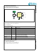
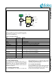
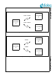
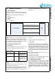
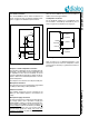
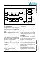
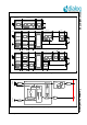
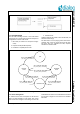
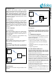
Table Of Contents
- 1.0 Connection diagram
- 2.0 Introduction
- 3.0 Cordless Voice Module functionality
- 4.0 Functional description
- 5.0 CAT-iq
- 6.0 Specifications
- 6.1 General
- 6.2 Absolute Maximum ratings
- 6.3 Operating Conditions
- 6.4 Digital Input/Output Pins
- 6.5 Analog Front End
- Table 11: Microphone amplifier
- Table 12: Microphone amplifier (Operating Condition)
- Table 13: Microphone supply voltages
- Table 14: VREFp load circuit
- Table 15: LSRp/LSRn outputs
- Table 16: LSRp/LSRn load circuits
- Table 17: PAOUTp, PAOUTn outputs
- Table 18: PAOUTp, PAOUTn outputs (Note 19)
- Table 19: PAOUTp, PAOUTn external components
- 6.6 Battery management
- 6.7 Baseband Part
- 6.8 Radio (RF) Part
- 6.9 RF Power supply
- 6.10 RF channel frequencies
- 7.0 Design guidelines
- 8.0 Example Application Diagram
- 9.0 Notices to OEM
- 10.0 Package information
- 11.0 Revision history

SC14CVMDECT SF Cordless Voice Module
© 2012 Dialog Semiconductor B.V. 16 July 1, 2014 v1.6
4.3.1 Audio connection
The SC14CVMDECT SF PP audio connections are
shown in Figure 8. Refer to "Example Application Dia-
gram" on page 43 for detailed component values.
.
Earpiece or small loudspeaker connection
The earpiece loudspeaker can be connected either dif-
ferentially or single-ended. Dynamic loudspeakers with
an impedance of 30 can be connected, as well as
ceramic loudspeakers equivalent to 600 and 30 F.
Refer to Table 16 for a detailed specification or the ear-
piece loudspeakers.
The earpiece is connected to the LSRp and LSRn pins.
Microphone connection
The microphone can be connected either single-ended
via MICp or differentially to MICp and MICn.
Headset connection
The headset microphone must be connected to the
MICh pin. The headset earpiece is connected to the
LSRp.
Microphone supply connection
For active microphones a voltage source with high sup-
ply voltage rejection ratio is provided on supply pins
VREFp/VREFm. Filtering of internal and external refer-
ence voltages is provided by an internal capacitor. No
external capacitor shall be connected to pin VREFp. To
avoid audible switching noise it is important that the
ground supply signals are directly “star point” con-
nected to the VREFm and not via a common ground
plane. From this VREFm star point, one connection is
made to the common ground plane.
Loudspeaker connection
For the handsfree operation a 4 loudspeaker must
be connected to the PAOUTp and PAOUTn pins as
shown in Figure 9. The VDDPA is the supply pin.
Refer to Table 19 for a detailed specification of the
external components around the loudspeaker. These
components are necessary to guarantee the lifetime of
the module.
Figure 8 Audio connections
LSRn
LSRp
MICh
MICn
VREFm
MICp
VREFp
Figure 9 Loudspeaker connection
PAOUTp
PAOUTn
VDDPA
VSS/GND
C_VDDPA
Cs_PAOUT
Rs_PAOUT
Cs_PAOUT
Rs_PAOUT