
User's Manual
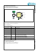
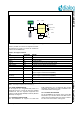
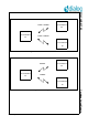
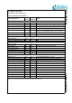
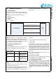
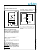
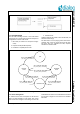
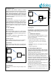
Table Of Contents
- 1.0 Connection diagram
- 2.0 Introduction
- 3.0 Cordless Voice Module functionality
- 4.0 Functional description
- 5.0 CAT-iq
- 6.0 Specifications
- 6.1 General
- 6.2 Absolute Maximum ratings
- 6.3 Operating Conditions
- 6.4 Digital Input/Output Pins
- 6.5 Analog Front End
- Table 11: Microphone amplifier
- Table 12: Microphone amplifier (Operating Condition)
- Table 13: Microphone supply voltages
- Table 14: VREFp load circuit
- Table 15: LSRp/LSRn outputs
- Table 16: LSRp/LSRn load circuits
- Table 17: PAOUTp, PAOUTn outputs
- Table 18: PAOUTp, PAOUTn outputs (Note 19)
- Table 19: PAOUTp, PAOUTn external components
- 6.6 Battery management
- 6.7 Baseband Part
- 6.8 Radio (RF) Part
- 6.9 RF Power supply
- 6.10 RF channel frequencies
- 7.0 Design guidelines
- 8.0 Example Application Diagram
- 9.0 Notices to OEM
- 10.0 Package information
- 11.0 Revision history

SC14CVMDECT SF Cordless Voice Module
© 2012 Dialog Semiconductor B.V. 15 July 1, 2014 v1.6
4.0 Functional description
4.1 UART INTERFACE
The UART is normally used for API commands, but
can also be used for software upgrades and debug-
ging.
The UART is a full duplex UART with frame type:
1 start bit,
8 data bits (LSB first),
1 stop bit,
no parity,
up to 115.2 kBd.
The UART hardware interface uses only TX/RX
(see Figure 7).
Caution: All signals are 1.8 V (see Table 8, Table 9
and Table 10). An external V.24 line driver must be
provided if the UART port of the module is connected
to a standard V.24 device. Connecting the module
without a driver may damage the module.
4.2 VES (VIRTUAL EEPROM Storage)
4.2.1 VES layout
The SC14CVMDECT SF PP and FP include a 4 kB
VES which is divided into two areas (see Table 5).
VES is supported as virtual EEPROM with the internal
FLASH.
A detailed overview of the VES parameters can be
found in document reference [4].
Some parts of the VES parameters are read into the
SC14CVMDECT SF during the start up and other parts
are used by the SC14CVMDECT SF software during
execution.
The VES parameters are divided into 2 types:
• Factory type
• Normal type
The factory type is specific for the SC14CVMDECT SF
and should only be set by production. The factory type
parameters are either adjustments used by the base-
band or the radio interface, or are used to set up the
SC14CVMDECT SF into special modes. The factory
type parameters will only be modified by changing the
factory programmed default value. See document ref-
erence [4].
The “normal” VES parameters can be reset to their
default values via software.
4.2.2 VES access by MCU
The host is able to read or modify the VES parameters
or limited free VES areas via API command.
4.3 AUDIO CONFIGURATIONS
The SC14CVMDECT SF audio supports standard
DECT audio qualities. The audio gain and volume
parameters are placed in the VES. The DECT gains
can be adjusted to meet the TBR38 and TBR10 audio
level requirements by using the SC14CVMDECT SF
application reference design. For other line and acous-
tic designs it is required to adjust and tune the audio
setup.
Figure 7 UART hardware configuration
SC14CVMDECT MCU
TX (serial out), module pin 48
RX (serial in), module pin 47
GND
Table 5: VES map
VES space Size Usage
SC14CVMDECT
SF
3.6 kB Used for RF, audio,
battery, tone setup,
data base, etc.
User 0.4 kB Can be used for
MMI applications
such as User infor-
mation.