
User's Manual
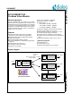
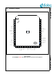
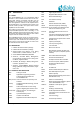
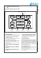
Table Of Contents
- 1.0 Connection diagram
- 2.0 Introduction
- 3.0 Cordless Voice Module functionality
- 4.0 Functional description
- 5.0 CAT-iq
- 6.0 Specifications
- 6.1 General
- 6.2 Absolute Maximum ratings
- 6.3 Operating Conditions
- 6.4 Digital Input/Output Pins
- 6.5 Analog Front End
- Table 11: Microphone amplifier
- Table 12: Microphone amplifier (Operating Condition)
- Table 13: Microphone supply voltages
- Table 14: VREFp load circuit
- Table 15: LSRp/LSRn outputs
- Table 16: LSRp/LSRn load circuits
- Table 17: PAOUTp, PAOUTn outputs
- Table 18: PAOUTp, PAOUTn outputs (Note 19)
- Table 19: PAOUTp, PAOUTn external components
- 6.6 Battery management
- 6.7 Baseband Part
- 6.8 Radio (RF) Part
- 6.9 RF Power supply
- 6.10 RF channel frequencies
- 7.0 Design guidelines
- 8.0 Example Application Diagram
- 9.0 Notices to OEM
- 10.0 Package information
- 11.0 Revision history

SC14CVMDECT SF Cordless Voice Module
© 2012 Dialog Semiconductor B.V. 10 July 1, 2014 v1.6
3.0 Cordless Voice Module function-
ality
This section describes the key functions and features
supported by the SC14CVMDECT SF as shown in Fig-
ure 2.
3.1 MODULE HARDWARE
The SC14CVMDECT SF internal hardware consists of:
• An internal microprocessor is running from FLASH
and handles the API call coming from UART or
embedded user software.
• A 4 kB VES (Virtual EEPROM Storage) used by the
protocol stack and for user variables.
• A DSP for the audio signal processing like ADPCM
voice compression towards the CODEC.
• A CODEC converts the analog signals to digital sig-
nals and vise versa.
• Input/Output ports which can be toggled high/low as
an output or a high/low digital level can be read as
an input.
• A 20.736 MHz XTAL. This crystal is automatically
tuned by the PP module software for optimal radio
performance.
• Voltage regulators convert the external supply volt-
age (VBAT) to stable supply voltages for the core
and the I/Os.
• A DECT radio transceiver with a built-in antenna cir-
cuit. The antenna itself is integrated into the module,
relieving the product designer from RF expertise.
• A full duplex UART for communication with an
optional host processor.
3.2 SOFTWARE CONTROL
The application software is written by the customer and
has to manage the call control and also the MMI func-
tions. The supported API software includes the Net-
work layer that is defined in figure 1 of the EN300 175-
3 document, which describes the DECT protocol stack.
Detailed functions and data flows, including some
example sequences, can be found in document refer-
ence [1] for FP and [2] for PP.
3.3 DECT PROTOCOL STACK
The SC14CVMDECT SF internal protocol stack is
based on the ETSI DECT specifications and is compli-
ant with ETSI 300 444 (GAP).
The product supports up to 6 DECT GAP compliant PP
units to one FP station.
Figure 2 SC14CVMDECT SF functional overview
FLASH User SW UART XTAL
Phoenix Host API
CODEC / PCM
API commands
UART interface to host
SPI
Ports
Port PinsPCM PortHead SetDECT RF
DSP
Protocol
Stack
Radio