
User's Manual
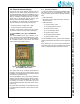
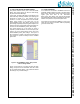
Table Of Contents

AN-D-211 External Antenna Design and Leveraging Modular Approval for CVMDECT
© 2013 Dialog Semiconductor B.V. Company Confidential 5 June 28, 2013 v0.2
3.0 External Antenna Design
FCC-04-165 now allows different antennas may be
certified with one module. Dialog Semiconductor B.V.
has obtained Modular Approval for CVMDECT using a
specific external printed antenna. FCC-04-165 dictates
that the certification measurements must to be per-
formed with the highest gain antenna and any other
antenna must have a similar radiation pattern.
For CVMDECT, this implies that an external antenna
may be connected to radio module, provided that:
• the antenna gain is not higher than -1.2dBi
• the antenna type is a (printed) monopole
In addition, if the antenna connection is user accessi-
ble, then the antenna connector shall be proprietary.
3.1 SC14CVMDECT_AF01_SF01 CONVERSION
BOARD
The “SC14CVMDECT_AF01_SF01” design is a con-
version PCB that holds a SC14CVMDECT SF xx mod-
ule on the top side, while having an SC14CVMDECT
AF compatible footprint on the bottom side. Please
refer to the following indicative picture:
Figure 1 SC14CVMDECT_AF01_SF01 with
SC14CVMDECT SFxx module
This design also has an embedded printed antenna
(located to the top right in the above picture) so that
CVMDECT can support FAD and may have increased
performance to operate as an FP.
The SC14CVMDECT_AF01_SF01 design passed the
Modular Approval testing and can be used as a drop-in
replacement for the SC14CVMDECT AF module with-
out needing to recertify the end-product (for those
countries allowing Modular Approvals, please refer to
section 2.3).
The gerber files of this design can be obtained through
your Dialog Semiconductor B.V. sales contact or repre-
sentative.
3.1.1 Boundary Conditions
In order to be allowed to leverage the CVMDECT Mod-
ular Approval for the SC14CVMDECT_AF01_SF01
design, the PCB should meet the following specifica-
tions:
• PCB material: FR4
• Dimensions: length x width x thickness = 25.9mm x
25.0mm x 0.8mm
• PCB layer stackup:
• L1 copper thickness: 18um
• L1-L2 prepreg thickness: 163um
• L2 copper thickness: 35um
• L2-L3 core thickness: 360um
• L3 copper thickness: 35um
• L3-L4 prepreg thickness 163um
• L4 copper thickness: 18um
The SC14CVMDECT_AF01_SF01 has been designed
using 6mil lines/space and 0.25mm end-size drill holes
rules.
When deviating in any way from these specifications,
the Modular Approval will be invalidated and recertifi-
cation on end-product/system level will be required.