
User's Manual
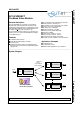
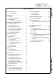
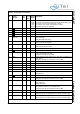
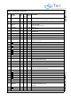
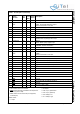
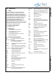
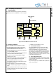
Table Of Contents
- 1.0 Connection Diagram
- 2.0 Introduction
- 3.0 Cordless Voice Module functionality
- 4.0 Functional description
- 5.0 CAT-iq
- 6.0 Specifications
- 7.0 Design guidelines
- 8.0 Audio Level Adjustment
- 9.0 Example Application Diagram
- 10.0 Mechanical Dimensions
- 11.0 Module integration
- 12.0 UTAM membership waiver
- 13.0 Soldering
- 14.0 Notices to OEM

SC14CVMDECT Cordless Voice Module
© 2011 SiTel Semiconductor B.V. Company Confidential 9 August 19, 2011 v1.2.1
3.0 Cordless Voice Module
functionality
This section describes the key functions and features
supported by the SC14CVMDECT as shown in Figure
2.
3.1 MODULE HARDWARE
The SC14CVMDECT internal hardware consist of:
• An Internal Microprocessor (MCU) running from
FLASH handling the AT command interpreter, the
protocol stack and further internal control.
• A 4kByte EEPROM used by the protocol stack and
for user EEPROM variables.
• A DSP for the Audio signal processing like ADPCM
voice compression towards the Codecs.
• A codec to convert the analog signals to digital
signals and vise versa.
• Input/Output ports which can be toggled high/low if
output or a high/low digital level can be read.
• A 10.368 MHz XTAL clock. This crystal is
automatically tuned by the module software for the
best Radio Performance.
• Voltage regulators to convert the external supply
voltage to a stable supply voltages for the core and
I/O’s.
• A DECT Radio transceiver with two built-in antenna
circuits. The antenna’s are on the module, so no RF
knowledge is required.
• A UART for communication to a host.
3.2 SOFTWARE CONTROL
The SC14CVMDECT can be controlled via an AT
Command Set over the UART interface or from the
internal user application. The external controller
handles the user interface (MMI) and sends/receives
AT commands and responses to the internal protocol
stack. A detailed functional and data flow description,
including an example of the start-up sequence, can be
found in document reference [1].
3.3 DECT PROTOCOL STACK
The SC14CVMDECT internal protocol stack is based
on the ETSI DECT specifications and is compliant with
ETSI 300 444 (GAP).
The product supports up to 6 DECT GAP compliant PP
units to one FP station.
Figure 2 SC14CVMDECT functional overview
UART interface
to host
AT commands
AT command
interpreter
Radio
Protocol
Stack
DSP
Ports
DECT
EEPROM
XTAL
FLASH
Codec
User
MIC
LSR
Headset
Control
UART
SW
SPI