
User's Manual
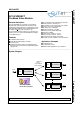
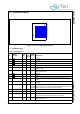
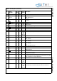
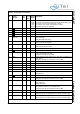
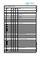
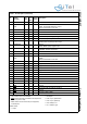
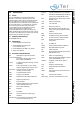
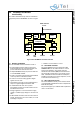
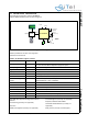
Table Of Contents
- 1.0 Connection Diagram
- 2.0 Introduction
- 3.0 Cordless Voice Module functionality
- 4.0 Functional description
- 5.0 CAT-iq
- 6.0 Specifications
- 7.0 Design guidelines
- 8.0 Audio Level Adjustment
- 9.0 Example Application Diagram
- 10.0 Mechanical Dimensions
- 11.0 Module integration
- 12.0 UTAM membership waiver
- 13.0 Soldering
- 14.0 Notices to OEM

SC14CVMDECT Cordless Voice Module
© 2011 SiTel Semiconductor B.V. Company Confidential 7 August 19, 2011 v1.2.1
• “NC” means: leave unconnected.
• GND
means internally connected to Ground plane of
module (51 pins in total)
• GND means connect to Ground (not supported,
functional pin)
Reset States:
• I = Input
• O= Output
• I-PD = Input, pulled down
• I-PU = Input, pulled up
• O-0 = Output, low
• O-1 = Output, high
J7 GND
-- -Ground
J8 P2[1] / PWM1 /
LED4
IO 8 I I/O Port
PWM1: Pulse Width Modulation output
LED4: 2.5/5mA LED current sink
J9 GND
-- -Ground
J10 GND
-- -Ground
J11 GND
-- -Ground
K1 VREFp O - I Positive microphone supply voltage
K2 MICp I - I Positive microphone input
K3 P3[2]/CIDINp IO 8 I I/O Port
CIDINp: Caller id opamps positive input
K4 P3[6]/RINGn IO 3 I I/O Port
RINGn: RING opamp negative input
K5 P3[4]/PARADET IO 8 I I/O Port
PARADET: Parallel set detection
K6 NC - - - leave unconnected
K7 NC - - - leave unconnected
K8 P2[0]/ PWM0 /
LED3
IO 8 I I/O Port
PWM0: -
LED3: 2.5/5mA LED current sink
K9 GND
-- -Ground
K10 NC - - - No ground under the pad (RF sensitive)
K11 NC - - - No ground under the pad (RF sensitive)
L1 GND
-- -Ground
L2 MICn I - I Negative handset microphone input
L3 GND
-- -Ground
L4 GND
-- -Ground
L5 NC - - - RF pad, must be left unconnected
L6 GND
-- -Ground
L7 GND
-- -Ground
L8 NC - - - leave unconnected
L9 GND
-- -Ground
L10 NC - - - No ground under the pad (RF sensitive)
L11 GND
-- -Ground
M2 NC - - - RF pad, no pad on PCB
Table 1: Pin description (Continued)
Pin
Module
Pin name
In/
Out
Iout
Drive
(mA)
Reset
State
Description