
User's Manual
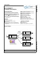
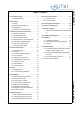
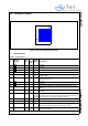
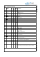
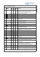
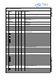
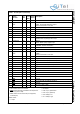
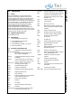
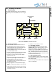
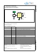
Table Of Contents
- 1.0 Connection Diagram
- 2.0 Introduction
- 3.0 Cordless Voice Module functionality
- 4.0 Functional description
- 5.0 CAT-iq
- 6.0 Specifications
- 7.0 Design guidelines
- 8.0 Audio Level Adjustment
- 9.0 Example Application Diagram
- 10.0 Mechanical Dimensions
- 11.0 Module integration
- 12.0 UTAM membership waiver
- 13.0 Soldering
- 14.0 Notices to OEM

SC14CVMDECT Cordless Voice Module
© 2011 SiTel Semiconductor B.V. Company Confidential 5 August 19, 2011 v1.2.1
D4 CHARGE I - I-PD
(270k
fixed
pull-
down)
Charger connected indication. Switches on the device if voltage >
1.5v. Must be connected to charger via resistor R>(Vcharger_max-
3V)/10 mA (round to next largest value in range).
If no charger used, Leave unconnected if not used.
Charger is currently not supported.
D5 GND
-- -Ground
D6 GND
-- -Ground
D7 GND
-- -Ground
D8 GND
-- -Ground
D9 P2[4]/SCL1/
PCM_DO
IO 8 I-PU I/O port
SCL1; I2C clock
PCM_DO: PCM Data output
D10 VDD O - - Digital Core supply voltage (1.8V TYP).
Output
from internal regulator.
D11 P2[5]/PCM_FSC IO 8 I-PU I/O Port
PCM_FSC: PCM Frame Sync
E1 VDDPA I - - CLASSD Audio Amplifier supply voltage up to 3.45V.
E2 GND
-- -Ground
E3 CHARGE_CTRL O - O-0 Charge control pin.
Leave unconnected if not used.
Charger is currently not supported.
E4 SOCn I - I Battery State Of Charge negative input. Star point connected to the
SOC resistor.
Charger is currently not supported: connect to GND
E5 GND
-- -Ground
E6 GND
-- -Ground
E7 GND
-- -Ground
E8 GND
-- -Ground
E9 GND
-- -Ground
E10 P0[7] / SPI_DI IO 8 I-PU I/O Port
SPI Data Input
E11 GND
-- -Ground
F1 SOCp I - I Battery State of charge positive input.
Charger is currently not supported: connect to GND
F2 P1[0]/INT0/ADC1 IO 2 I-PU I/O Port
INT0: Interrupt 0
ADC1; ADC input 1
F3 ADC2/NTC I - I ADC2
NTC protection input for Li-Ion charger circuit.
Charger is currently not supported: connect to GND
F4 NC - - - leave unconnected
F5 ULP_PORT I - I Ultra Low Power Port Pin
Ultra low power is not supported by the software, connect to gnd.
F6 ULP_VBAT I - I Ultra Low Power Supply Pin
Ultra low power is not supported by the software, connect to gnd.
Table 1: Pin description (Continued)
Pin
Module
Pin name
In/
Out
Iout
Drive
(mA)
Reset
State
Description