
User's Manual
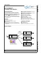
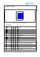
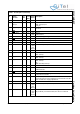
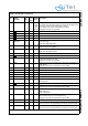
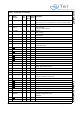
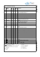
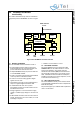
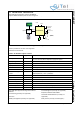
Table Of Contents
- 1.0 Connection Diagram
- 2.0 Introduction
- 3.0 Cordless Voice Module functionality
- 4.0 Functional description
- 5.0 CAT-iq
- 6.0 Specifications
- 7.0 Design guidelines
- 8.0 Audio Level Adjustment
- 9.0 Example Application Diagram
- 10.0 Mechanical Dimensions
- 11.0 Module integration
- 12.0 UTAM membership waiver
- 13.0 Soldering
- 14.0 Notices to OEM

SC14CVMDECT Cordless Voice Module
© 2011 SiTel Semiconductor B.V. Company Confidential 4 August 19, 2011 v1.2.1
B5 GND -- -Ground
B6 P2[6]/INT6 /
WTF_IN
IO 2 I-PU I/O port
INT6: Interrupt Input.
WTF_IN: -
B7 P0[5] / SPI_CLK IO 8 I-PU I/O Port
SPI Clock
B8 GND
-- -
B9 P0[1] / URX IO 8 I-PD
(10k)
I/O port
UART Serial In
B10 VBATT I - - Secondary supply voltage. Connect to VCCRF.
B11 GND
-- -Ground
B12 NC - - - RF pad, no pad on PCB
C1 GND
-- -Ground
C2 PAOUTn IO 500 O-0 (5k
fixed
pull-
down)
CLASSD loudspeaker positive output
C3 GND
-- -Ground
C4 P2[7]/INT7 IO 8 I-PU I/O port
INT7: Interrupt
C5 P1[4]/INT4 IO 1/2 I-PD I/O port
INT4: Interrupt
C6 P1[1]/INT1 IO 2 I-PU I/O Port
INT1: Interrupt
LE: -
INT6: secondary Interrupt
C7 GND
-- -Ground
C8 P0[0] / UTX O 8 I-PU I/O Port
UART Serial Out
C9 GND
-- -Ground
C10 JTAG IO 8 I-PU JTAG-SDI+; one wire Debug interface with open-drain.
Pullup with R=1k to Vdd.
C11 VCCRF I - - RFSUPPLY input < 3.45V. Connect to VBAT if VBAT less than
3.45V. Else this pin must be supplied from and external 3.3V LDO.
Refer to Table 16 for supply requirements.
D1 GND
-- -Ground
D2 PAOUTp IO 500 O-0 (5k
fixed
pull-
down)
CLASSD loudspeaker positive outputs
D3 PON I I (270k
fixed
pull-
down)
Power on, Switches on the device if Voltage > 1.5V.
May be directly connected to VBAT, also with Li-Ion batteries
Table 1: Pin description (Continued)
Pin
Module
Pin name
In/
Out
Iout
Drive
(mA)
Reset
State
Description