
User's Manual
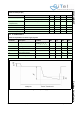
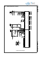
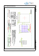
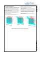
Table Of Contents
- 1.0 Connection Diagram
- 2.0 Introduction
- 3.0 Cordless Voice Module functionality
- 4.0 Functional description
- 5.0 CAT-iq
- 6.0 Specifications
- 7.0 Design guidelines
- 8.0 Audio Level Adjustment
- 9.0 Example Application Diagram
- 10.0 Mechanical Dimensions
- 11.0 Module integration
- 12.0 UTAM membership waiver
- 13.0 Soldering
- 14.0 Notices to OEM

SC14CVMDECT Cordless Voice Module
© 2011 SiTel Semiconductor B.V. Company Confidential 35 August 19, 2011 v1.2.1
7.0 Design guidelines
This section describes the software and hardware
considerations taken into account when designing the
target application.
The SC14CVMDECT can be used standalone or next
to an MCU that controls the module. In case the
module is used standalone the application will be
stored in its on-board Flash. In total 324kBytes of Flash
are available for this.
Applications can be written with the Athena software
development environment (see [4]).
7.1 APPLICATION SOFTWARE FOR PP
In a PP application the following software tasks must
be handled by the MCU or within the module itself:
• UART communication (external microprocessor
only)
• PP MMI
• Display interface (optional)
• Keyboard interface (optional)
• Battery Charge interface (optional)
• Audio handling
• Tone / Melodies handling
For control commands see document reference [1].
UART communication
The UART communication is the main control interface
of the SC14CVMDECT.
PP MMI
The MMI state machine must handle the call setup and
call termination on the PP.
Display Interface
The MCU / PP handles the display interface including
the display driver.
Keyboard Interface
The MCU/ PP handles the keyboard interface including
the keyboard driver.
Battery Charge handling
SC14CVMDECT V3 supports no battery management.
This must be done by and external charge circuit on
combination with the external MCU. The Application
Software must handle the MMI part such as battery
status for the user and the PP battery current
consumption states.
Audio handling
The Application Software state machine must control
when to open and close the audio. The headset plug-in
detection must handled by the host, and a status is
send to the PP MMI from the PP. The PP MMI must
handle the volume control.
Headset detection boundaries can be adjusted in
EEPROM. When headset indication is received from
the PP Headset detection logic (future release), the
Application Software can decide if audio should be
switched to the headset and sends a request to the
SC14CVMDECT.
The PP audio handling basically consists of 4 audio
states (see Figure 9):
1. Idle (Alert) State
2. Earpiece State
3. Handsfree State (Speakerphone)
4. Headset State
Shifting between states is done through the API.
Please refer to the PP application layout for pin
connections.
Tone handling
The Application Software state machine must control
when to play tones and the volume setting. Custom
melodies can be defined in the EEPROM.
7.2 APPLICATION SOFTWARE FOR FP
In an FP application the following software tasks must
be handled by the MCU or within the module itself:
• UART communication (external microprocessor
only)
•FP MMI
• Display interface (optional)
• Keyboard interface (optional)
• Audio handling
• Tone / Melodies handling
For control commands see document reference [1].
UART Communication
The UART communication forms the basic of the FP
operation because via this interface the
SC14CVMDECT is controlled.
PP MMI
The MMI state machine must handle the call setup and
call termination on the FP.
Display Interface
The MCU/ FP handles the display interface including
the display driver.
Keyboard Interface
The MCU/ FP handles the keyboard interface including
the keyboard driver.
Audio Handling
The Application Software state machine must control
when to open and close the audio. The headset plug-in
detection is handled by the FP, and a status is send to
the FP MMI from the FP. The FP MMI must handle the