
User's Manual
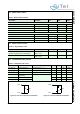
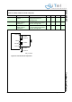
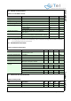
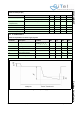
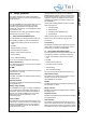
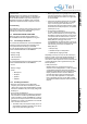
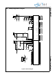
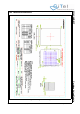
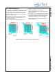
Table Of Contents
- 1.0 Connection Diagram
- 2.0 Introduction
- 3.0 Cordless Voice Module functionality
- 4.0 Functional description
- 5.0 CAT-iq
- 6.0 Specifications
- 7.0 Design guidelines
- 8.0 Audio Level Adjustment
- 9.0 Example Application Diagram
- 10.0 Mechanical Dimensions
- 11.0 Module integration
- 12.0 UTAM membership waiver
- 13.0 Soldering
- 14.0 Notices to OEM

SC14CVMDECT Cordless Voice Module
© 2011 SiTel Semiconductor B.V. Company Confidential 31 August 19, 2011 v1.2.1
6.2 DIGITAL INPUT LEVELS
6.3 DIGITAL OUTPUT LEVELS
6.4 LOUDSPEAKER LOAD CIRCUITS
Table 9: DIGITAL INPUT LEVELS
Description Condition Min Max Units
Logic 0 input level
all digital pads, except PON, CHARGE VDD=1.8V 0.3 x VDD V
PON 0.9 V
CHARGE 0.9 V
RSTn 0.2 x VDD V
Logic 1 input level
all digital pads, except PON, CHARGE VDD = 1.8 V 0.7 x VDD V
PON 1.5 V
CHARGE 1.5 V
RSTn 0.8xVDD V
Table 10: Digital Output Levels
Descriptions Conditions Min Max Units
Logic 0 output level
(For drive capability see pin description)
Iout = 2,4,8 mA
VDD = 1.8 V
0.2 x VDD V
Logic 1 output level Iout = 2,4,8 mA
VDD = 1.8 V
0.8 x VDD V
Table 11: LSRp/LSRn load circuits
PARAMETER DESCRIPTION CONDITIONS MIN TYP MAX UNITS
Cp1_Rl1_inf Load capacitance see Figure 22, R
L1
= 30 pF
Cp1_Rl1_1k Load capacitance see Figure 22, R
L1
k 100 pF
Rl1 Load resistance 28
Cp2 Parallel load
capacitance
see Figure 23 30 pF
Cs2 Serial load capacitance 30 F
Rl2 Load resistance 600
Figure 22 Load circuit A Dynamic loudspeaker
R
L1
C
p1
LSRp
LSRn
Figure 23 Load circuit B Piezo loudspeaker
C
s2
LSRp
LSRn
R
L2
C
p2