
User's Manual
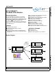
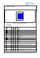
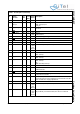
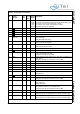
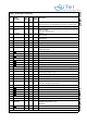
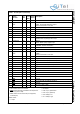
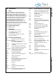
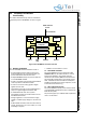
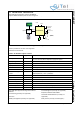
Table Of Contents
- 1.0 Connection Diagram
- 2.0 Introduction
- 3.0 Cordless Voice Module functionality
- 4.0 Functional description
- 5.0 CAT-iq
- 6.0 Specifications
- 7.0 Design guidelines
- 8.0 Audio Level Adjustment
- 9.0 Example Application Diagram
- 10.0 Mechanical Dimensions
- 11.0 Module integration
- 12.0 UTAM membership waiver
- 13.0 Soldering
- 14.0 Notices to OEM

SC14CVMDECT Cordless Voice Module
© 2011 SiTel Semiconductor B.V. Company Confidential 3 August 19, 2011 v1.2.1
1.0 Connection Diagram
1.1 PIN DESCRIPTION
Figure 1 Connection Diagram (Bottom View)
M
L
K
J
H
G
F
E
D
C
B
A
121110 9 8 7 6 5 4 3 2 1
Table 1: Pin description
Pin
Module
Pin name
In/
Out
Iout
Drive
(mA)
Reset
State
Description
A1 GND
-- -Ground
A2 GND
-- -Ground
A3 GND
-- -Ground
A4 NC - - I leave unconnected
A5 VDDIO I - - Supply voltage for internal QSPI and data flash. Must be connected
to VDD (1.8V).
A6 P1[2]/INT2 IO 2 I-PU I/O port.
INT2: Interrupt Input.
A7 GND
-- -Ground
A8 GND
-- -Ground
A9 VBAT I - - Main supply voltage <5.5V. Can be directly connected to a Li-Ion
battery.
A10 P0[4] / SPI_EN IO 8 I-PU I/O port
SPI_EN
A11 RSTn I 1 I-PU
(200k
pull-up)
Active low Reset input with Schmitt-trigger input, open-drain output
and pull up resistor to internal VDD. Input may not exceed 2.0 V. An
internal capacitor of 100nF is mounted on this pin.
B1 GND
-- -Ground
B2 GND
-- -Ground
B3 CP_VOUT1 O - I Charge Pump Output 1.
Must be connected through a capacitor of 1uF to gnd
B4 P1[5]/INT5 IO 8 O-1 I/O Port
INT5: Interrupt Input.