
User's Manual

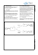


Table Of Contents
- 1.0 Connection Diagram
- 2.0 Introduction
- 3.0 Cordless Voice Module functionality
- 4.0 Functional description
- 5.0 CAT-iq
- 6.0 Specifications
- 7.0 Design guidelines
- 8.0 Audio Level Adjustment
- 9.0 Example Application Diagram
- 10.0 Mechanical Dimensions
- 11.0 Module integration
- 12.0 UTAM membership waiver
- 13.0 Soldering
- 14.0 Notices to OEM

SC14CVMDECT Cordless Voice Module
© 2011 SiTel Semiconductor B.V. Company Confidential 23 August 19, 2011 v1.2.1
The following data connections are supported:
• PP to PP (point to point)
• FP to PP, PP to FP
• PP to all PPs (broadcast)
• FP to all PPs (broadcast)
All communication is routed via the FP. The FP has
number #6. See Figure 14.
4.7.5 Broadcasting messages
The broadcast message is 19 bytes at a time and can
real-time clock from the FP to the PP when the real-
time clock is activated.
When broadcasting data no active connections are
established.
The data is transmitted from the FP and received by
any registered PP. The communication is only one
way. Therefore, the broadcast data is not secured
because there is no retransmission.
If the PP does not receive it right the first time, the
broadcast data is lost.
4.7.6 IWU to IWU messaging
The protocol in the SC14CVMDECT module is made
according to the DECT/GAP standard as defined in
EN 300 175 and EN 300 444.
The DECT standard defines an EMC code (see
EN 300 175-5, chapter 7.7.23.). This code is unique for
a DECT product and must be programmed by the
DECT manufacturer to the correct manufacturer code.
The EMC code must be the same for SC14CVMDECT
based product families when using the IWU to IWU
messaging.
If the SiTel default EMC EEPROM value is changed
the IWU to IWU messaging may not operate correctly.
IWU data is transferred in a FA format frame; see
chapter 6.1 in EN 300 175-4. This frame has an
information field of maximum 63 bytes of which
maximum 52 bytes can be used for IWU data. With the
SC14CVMDECT it is only possible to send 5 frames in
a row without pause. The following frame must be an
acknowledge-frame to secure that the internal buffers
within the SC14CVMDECT are emptied.
The FA frame is segmented in 5 bytes fragments and
transferred over the air-interface in the A-field. The 2-
bytes CRC is used to determine if the data is received
correct. If the data is not received correct this is
signalled back to the transmitter by the Q2 bit, and the
data is retransmitted.
The FA frame has a 2 bytes checksum, used to
determine if the complete packet is received correct. If
A checksum error is signalled back to the transmitter
and the complete packet is retransmitted. The packet
will re-transmit until it is received correctly, or the link is
closed.
More transmitted packets will be received in the same
order as they were transmitted. The application must
handle flow control, if needed.
4.8 REGISTRATION
The PP and the FP must be paired using a procedure
called Registration. Without Registration, the PP will be
out-of-lock and will not be able to establish a link to a
FP and therefore not be able to make a call. The
registration uses the unique product identities and
secures the PP and FP to allow no cross-
communication. To avoid cross-communication it is
very important that all the PPs and the FP use an
unique numbering scheme.
The PP can be deregistered from a FP either via the
FP or PP MMI Software using the command interface.
It is also possible to deregister a PP from another
registered PP.
It is possible to pair a PP and FP during the production.
4.8.1 Handling product identities
To secure that the FP and PPs do not make cross-
communications a unique ID must be entered into the
EEPROM of an FP or PP. For the DECT version the ID
for the FP is named RFPI and for the PP the ID is
named IPEI. These numbers are factory settings.
After a successful registration, the IPEI is stored in the
FP and the RFPI is stored in the PP. In this way the two
parts are known to each other and are allowed to make
connections. The registration data are automatically
stored in EEPROM of the FP and PP while making the
registration.
It is possible to register the same PP to 2 FPs, but it
can only be used in one FP at the same time.
Figure 14 Data connection PP0 to PP1 or all
FP
#6
PP
#3
PP
#4
PP
#5
PP
#0
PP
#1
PP
#2