
User's Manual
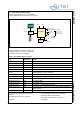
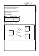
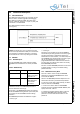
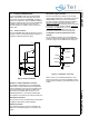
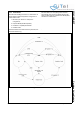
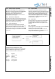
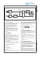
Table Of Contents
- 1.0 Connection Diagram
- 2.0 Introduction
- 3.0 Cordless Voice Module functionality
- 4.0 Functional description
- 5.0 CAT-iq
- 6.0 Specifications
- 7.0 Design guidelines
- 8.0 Audio Level Adjustment
- 9.0 Example Application Diagram
- 10.0 Mechanical Dimensions
- 11.0 Module integration
- 12.0 UTAM membership waiver
- 13.0 Soldering
- 14.0 Notices to OEM

SC14CVMDECT Cordless Voice Module
© 2011 SiTel Semiconductor B.V. Company Confidential 17 August 19, 2011 v1.2.1
4.3 PP AUDIO CONFIGURATIONS
The SC14CVMDECT audio is supporting standard
DECT audio qualities. The audio gain and volume
parameters are placed in the EEPROM. The DECT
gains can be adjusted to meet the TBR38 and TBR10
audio level requirements by using the SC14CVMDECT
application reference design. For other line and
acoustic designs it is needed to adjust and tune the
audio setup.
4.3.1 Audio connection
The SC14CVMDECT PP audio connections are show
in Figure 7. Refer to “Example Application Diagram” on
page 38 for detailed component values.
.
Earpiece or small loudspeaker connection
The earpiece loudspeaker can be connected either
differentially or single-ended. Dynamic loudspeakers
with an impedance of 30 can be connected as well
as ceramic loudspeakers equivalent to 600 and
30 F can be connected. Refer to Table 11 for a
detailed specification or the earpiece loudspeakers.
The earpiece is connected to the LSRp and LSRn pins.
Microphone connection
The microphone can be connected either single-ended
via MICp or differentially to MICp and MICn
Headset connection
The headset microphone must be connected to the
MICh pin. The headset earpiece is connected to the
LSRp.
Microphone supply connection
For active microphones a voltage source with high
supply voltage rejection ratio is provided on supply pins
VREFp/VREFm. Filtering of internal and external
reference voltages is provided with internal capacitor.
No external capacitor
shall be connected to the
VREFp. To avoid audible switching noise it is important
that the ground supply signals are directly “star point”
connected to the VREFm and not via a common
ground plane. From this VREFm star point, one
connection is made to the common ground plane.
Loudspeaker connection (supported in future
releases)
For the handsfree operation an 4 ohm loudspeaker
must be connected to the PAOUTp and PAOUTn pins
as shown in Figure 8. The VDDPA is the supply pin.
Refer to Table 12 for a detailed specification of the
external components around the loudspeaker. These
components are necessary to guarantee lifetime of the
module.
Figure 7 Audio connections
LSRn
LSRp
MICh
MICn
VREFm
MICp
VREFp
Figure 8 Loudspeaker connection
PAOUTp
PAOUTn
VDDPA
VSS/GND
C_VDDPA
Cs_PAOUT
Rs_PAOUT
Cs_PAOUT
Rs_PAOUT