
User's Manual
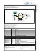
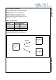
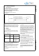
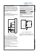
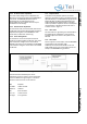
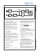
Table Of Contents
- 1.0 Connection Diagram
- 2.0 Introduction
- 3.0 Cordless Voice Module functionality
- 4.0 Functional description
- 5.0 CAT-iq
- 6.0 Specifications
- 7.0 Design guidelines
- 8.0 Audio Level Adjustment
- 9.0 Example Application Diagram
- 10.0 Mechanical Dimensions
- 11.0 Module integration
- 12.0 UTAM membership waiver
- 13.0 Soldering
- 14.0 Notices to OEM

SC14CVMDECT Cordless Voice Module
© 2011 SiTel Semiconductor B.V. Company Confidential 16 August 19, 2011 v1.2.1
4.0 Functional description
4.1 UART INTERFACE
The UART isnormally used for AT commands, but can
also be used for software upgrades and debugging.
The UART is a full duplex UART with frame type: 1
start bit, 8 data bits (LSB first), 1 stop bit, no parity and
a baud rate of 115.200 kBaud
The UART hardware interface uses 3 wires
(see Figure 6)
.
Caution: All signals are 1.8 V. An external V.24 line
driver must be provided if the UART port of the module
is connected to a standard V.24 device. Connecting
the module without a driver may damage the module.
4.2 EEPROM
4.2.1 EEPROM layout
The SC14CVMDECT PP and FP include a 4 Kbyte
EEPROM which is divided into two areas (see Table
6).
A detailed overview of the EEPROM parameter is
found in document reference [2].
Some parts of the EEPROM parameters are read into
the SC14CVMDECT during the start up and other parts
are used by the SC14CVMDECT software during
execution.
The EEPROM parameters are divided into 2 types:
• Factory type
• normal type.
The factory type is specific for the SC14CVMDECT
and should only be set by production. The factory types
are either parameters for adjustments used by the
baseband or the radio interface, or is used to setup the
SC14CVMDECT into special modes. The factory types
will only be modified by changing the factory
programmed default value. See document reference
[2]. Only users with “debug” authorization can modify
these EEPROM parameters
The other “normal” EEPROM parameters can be reset
to default values by running a soft default setting
(default batch file).
4.2.2 EEPROM access by MCU
The host is able to read or modify the EEPROM
parameters or limited free EEPROM areas via AT
commands AT+WEExx.
Access to the EEPROM parameters depends on the
authorization level set by the AT+WULA parameter:
0 = Anonymous User with Lowest Authority (not able to
read from and write to EEPROM)
1 = Power User. Able to read from all EEPROM
locations and write to locations 0x0F00..0x0FBF (user
space). Password:
748357.
2 = Debug User Highest Authority.Able to read from
and write to EEPROM (audio and stack related
parameters. Contact SiTel Semiconductor for the
password.
Figure 6 UART hardware configuration
Table 6: EEPROM map
EEPROM space Size Usage
SC14CVMDECT 3.6 Kbyte Used for RF, audio,
battery, tone setup,
data base, etc.
User 0.4 Kbyte. Can be used for
MMI applications
such as User
information.