
Data Sheet
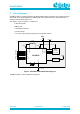
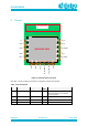
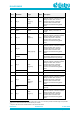
Table Of Contents
- General Description
- Key Features
- Applications
- Contents
- Figures
- Tables
- 1 References
- 2 Block Diagram
- 3 Pinout
- 4 Characteristics
- 5 Mechanical Specifications
- 6 Packaging Information
- 7 Application Information
- 8 Design Guidelines
- 9 Soldering
- 10 Ordering Information
- 11 Regulatory Information
- 12 Environmental Information
- 13 Bluetooth SIG Qualification
- Revision History

DA14531MOD
SmartBond TINY
TM
Module
Preliminary
Datasheet
Revision 2.1
4-June-2020
CFR0011-120-00
4 of 31
© 2020 Dialog Semiconductor
Figures
Figure 1: SmartBond TINY Module Block Diagram .............................................................................. 6
Figure 2: Pinout Diagram Top View ...................................................................................................... 7
Figure 3: Mechanical Drawing ............................................................................................................ 13
Figure 4: Module Footprint Top View ................................................................................................. 14
Figure 5: Module Shield Marking ........................................................................................................ 14
Figure 6: Tape and Reel ..................................................................................................................... 15
Figure 7: Reel labeling........................................................................................................................ 16
Figure 8: Mounting positions for optimum Antenna Performance ....................................................... 17
Figure 9: Antenna Performance proximity with copper(left), laminate(middle) and laminate under
antenna (right) .................................................................................................................................... 18
Figure 10: Tiny Module Evaluation Board........................................................................................... 18
Figure 11: VSWR mounted in the upper left corner (Position #1) of evaluation board ....................... 19
Figure 12: VSWR with module mounted in center (Position #2) of the evaluation board ................... 19
Figure 13: VSWR with module mounted in the upper right corner (Position #3) of the evaluation
board .................................................................................................................................................. 19
Figure 14: Measurement plane definition ........................................................................................... 20
Figure 15: Radiation pattern for XY-plane, horizontal polarization. .................................................... 21
Figure 16: Radiation pattern for XY-plane, vertical polarization.......................................................... 21
Figure 17: Radiation pattern for XZ-plane, horizontal polarization. ..................................................... 21
Figure 18: Radiation pattern for XZ-plane, vertical polarization. ......................................................... 21
Figure 19: Radiation pattern for YZ-plane, horizontal polarization. ..................................................... 21
Figure 20: Radiation pattern for YZ-plane, vertical polarization. ......................................................... 21
Figure 21: Recommended reflow profile for Lead Free Solder ........................................................... 22
Tables
Table 1: Pin Description ....................................................................................................................... 7
Table 2: Absolute Maximum Ratings .................................................................................................... 9
Table 3: Recommended Operating Conditions ................................................................................... 10
Table 4: DC Characteristics ................................................................................................................ 10
Table 5: XTAL32MHz - Recommended Operating Conditions ........................................................... 11
Table 6: Digital IO - Recommended Operating Conditions ................................................................. 11
Table 7: Digital IO - DC Characteristics .............................................................................................. 12
Table 8: Radio 1Mbps - AC Characteristics........................................................................................ 12
Table 9: Reel Specifications ............................................................................................................... 15
Table 10: Antenna efficiency vs Tiny Module positions ...................................................................... 17
Table 11: Reflow profile specification ................................................................................................. 22
Table 12: Ordering Information (Samples) ......................................................................................... 23
Table 13: Ordering Information (Production) ...................................................................................... 23
Table 14: Standards Conformance ..................................................................................................... 23