
Data Sheet
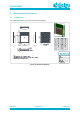
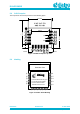
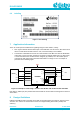
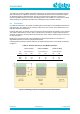
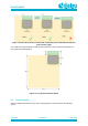
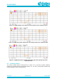
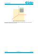
Table Of Contents
- General Description
- Key Features
- Applications
- Contents
- Figures
- Tables
- 1 References
- 2 Block Diagram
- 3 Pinout
- 4 Characteristics
- 5 Mechanical Specifications
- 6 Packaging Information
- 7 Application Information
- 8 Design Guidelines
- 9 Soldering
- 10 Ordering Information
- 11 Regulatory Information
- 12 Environmental Information
- 13 Bluetooth SIG Qualification
- Revision History

DA14531MOD
SmartBond TINY
TM
Module
Preliminary
Datasheet
Revision 2.1
4-June-2020
CFR0011-120-00
18 of 31
© 2020 Dialog Semiconductor
Figure 9: Antenna Performance proximity with copper(left), laminate(middle) and laminate
under antenna (right)
The actual Tiny module evaluation board layout that has been used to conduct measurements is
presented in the following figure:
Figure 10: Tiny Module Evaluation Board
8.2 Antenna graphs
Antenna VSWR measurements for the three mounting positions are described in the following
figures.