
Data Sheet
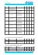
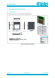
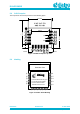
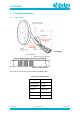
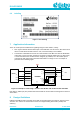
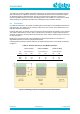
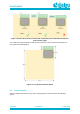
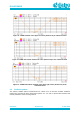
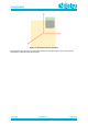
Table Of Contents
- General Description
- Key Features
- Applications
- Contents
- Figures
- Tables
- 1 References
- 2 Block Diagram
- 3 Pinout
- 4 Characteristics
- 5 Mechanical Specifications
- 6 Packaging Information
- 7 Application Information
- 8 Design Guidelines
- 9 Soldering
- 10 Ordering Information
- 11 Regulatory Information
- 12 Environmental Information
- 13 Bluetooth SIG Qualification
- Revision History

DA14531MOD
SmartBond TINY
TM
Module
Preliminary
Datasheet
Revision 2.1
4-June-2020
CFR0011-120-00
17 of 31
© 2020 Dialog Semiconductor
The PCB trace antenna radiated performance depends on the host PCB layout. Maximum antenna
gain is better than -0.5 dBi when mounted on a 50x50 mm reference board, as illustrated in Figure
19. Radiation pattern is omnidirectional. The RF front end has been optimized to achieve the
maximum possible efficiency for various mounting positions of the module on a host PCB. To obtain
similar performance, guidelines described in the following sections should be followed.
8.1 Placement
For optimum performance, the module should be placed at the edge of a host PCB with the antenna
edge facing out. The module can be located on either of the outer corners or the middle of the host
PCB with equivalent performance.
Proximity with copper or laminate next to the PCB trace antenna affects the efficiency of the antenna.
The antenna should have 4 mm free space in all directions. Laminate or copper under the antenna
should be avoided as it severely affects the performance of the antenna. Antenna keep-out area can
be seen in Figure 9.
Metals close to the antenna will cause degradation on antenna performance. The amount of
degradation depends on the host system characteristics.
Following table summarizes antenna efficiency for different placements on a host PCB as indicated
in Figure 8.
Table 10: Antenna efficiency vs Tiny Module positions
Position # 1 (Left)
Position # 2 (Middle)
Position # 3 (Right)
Freq
Antenna efficiency
Antenna efficiency
Antenna efficiency
[MHz]
[%]
[dB]
[%]
[dB]
[%]
[dB]
2405
52
-2,8
40
-4,0
40
-4,0
2440
46
-3,4
34
-4,7
41
-3,9
2480
50
-3,0
40
-4,0
52
-2,8
Figure 8: Mounting positions for optimum Antenna Performance