
Data Sheet
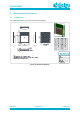
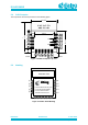
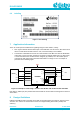
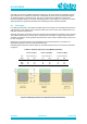
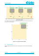
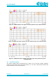
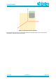
Table Of Contents
- General Description
- Key Features
- Applications
- Contents
- Figures
- Tables
- 1 References
- 2 Block Diagram
- 3 Pinout
- 4 Characteristics
- 5 Mechanical Specifications
- 6 Packaging Information
- 7 Application Information
- 8 Design Guidelines
- 9 Soldering
- 10 Ordering Information
- 11 Regulatory Information
- 12 Environmental Information
- 13 Bluetooth SIG Qualification
- Revision History

DA14531MOD
SmartBond TINY
TM
Module
Preliminary
Datasheet
Revision 2.1
4-June-2020
CFR0011-120-00
16 of 31
© 2020 Dialog Semiconductor
6.2 Labeling
Figure 7: Reel labeling
7 Application Information
There are some special considerations regarding using the TINY module, namely:
• RST signal is shared with the MOSI input of the NOR flash. For this reason, RST must not be
driven to GND. When internal Flash is in use, reset functionality is not available.
• The SPI Bus of DA14531 is used for the communication of the BLE SoC with the NOR Flash
at boot time. Three of the four signals are not driven to external module pins. For this reason,
a sensor that utilizes the SPI bus must be assigned (by software) on to the module pins to
communicate with after booting and when NOR Flash is no longer in use. An example is
presented in the following figure.
PROJECT
NAME
DA14531
1Mbit
NOR
Flash
P0_0/RST
P0_1
P0_3
P0_4
P0_2
P0_5
P0_6
P0_7
P0_8
P0_9
P0_10
P0_11
GND
VBAT
J12
J5
J13
J16
J15
J8
P25Q11U
MOSI
/CS
MISO
SCK
MOSI
/CS
MISO
SCK
J10
J14
J9
Sensor
DA14531 TINY Module
MCU
UTX
URX
GPIO
J1, J2, J3, J4, J6, J11
Figure 11: Example of connecting a sensor to the SPI bus and an MCU to RST and UART
Note that P0_0/RST pin (J12) should not be driven while the TINY module is booting from its internal
SPI FLASH.
8 Design Guidelines
DA14531 SmartBond TINY™ Module comes with an integrated PCB trace antenna. Antenna area is
12x4 mm. The antenna is characterized in terms of Voltage Standing Wave Ratio (VSWR) and
efficiency.